Service Manuals, User Guides, Schematic Diagrams or docs for : Tektronix publikacje TekDigitalConcepts
<< Back | HomeMost service manuals and schematics are PDF files, so You will need Adobre Acrobat Reader to view : Acrobat Download Some of the files are DjVu format. Readers and resources available here : DjVu Resources
For the compressed files, most common are zip and rar. Please, extract files with Your favorite compression software ( WinZip, WinRAR ... ) before viewing. If a document has multiple parts, You should download all, before extracting.
Good luck. Repair on Your own risk. Make sure You know what You are doing.
Image preview - the first page of the document
>> Download TekDigitalConcepts documenatation <<
Text preview - extract from the document
Digit a1
Concepts
A B X
0
I
0
I
0 -
0
I
I
0
0
0
X=AB=AB
I I I
B Y -
--
00
1 Y=AB=A+B
I I
0 I
I I I
OTHER BOOKS IN THIS SERIES:
Circuit Concepts
Power Supply Circuits
062-0888-01
Oscilloscope Cathode-Ray Tubes
062-0852-01
Storage Cathode-Ray Tubes and Circuits
062-0861-01
Television Waveform Processing Circuits
062-0955-00
Digital Concepts
062-1030-00
Spectrum Analyzer Circuits
062-1055-00
Oscilloscope Trigger Circuits
062-1056-00
Sweep Generator Circuits
062-1098-00
Measurement Concepts
Information Display Concepts
062-1005-00
Semiconductor Devices
062-1009-00
Television System Measurements
062-1064-00
Spectrum Analyzer Measurements
062-1070-00
Engine Analysis
062-1074-00
DIGITAL
CONCEPTS
BY
LEONARD W. BELL
Significant Contributions
by
JOHN W. SHEPPARD
FIRST EDITION SECOND PRINTING JUNE 1969
062-1030-00
PRICE $1.00
TEKTRONIX, INC.; 1968
BEAVERTON, OREGON
ALL RIGHTS RESERVED
CONTENTS
INTRODUCTION 1
THE BINARY NUMBER SYSTEM 3
BOOLEAN ALGEBRA 15
NAND GATE, NOR GATE, AND F L I P F L O P 31
IMPLEMENTING LOGIC FUNCTIONS 47
IMPLEMENTING LOGIC C I R C U I TS
USING INTEGRATED C I R C U IT S 71
7 COUNTING C I R C U I TS 91
8 COUNTER READOUT C I R C U I TS 107
INDEX 125
FORWARD
This the first edition o f the Tektronix Digital Concepts book
uses Negative True Logic when explaining circuits throughout
the book. This is due t o the fact that most digital instruments
designed at Tektronix prior t o the publication of this book
have had their circuits and logic diagrams explained in terms
of Negative True Logic.
This is not meant t o imply that Tektronix has standardized on
Negative True Logic. There are times when Positive True Logic
may be the more natural form t o use.
The content of the book is as valid for explaining the concept
of one system as for the other.
1
a
INTRODUCTION
Automated o r programmed d e v i c e s u s i n g i n t e g r a t e d
l o g i c c i r c u i t s (IC) become more common d a i l y . The
e n g i n e e r o r t e c h n i c i a n whose background l i e s l a r g e l y
w i t h c o n v e n t i o n a l o r analog-type c i r c u i t r y can have
d i f f i c u l t y u n d e r s t a n d i n g d i g i t a l diagrams f i l l e d
w i t h odd-shaped symbols. Most p e o p l e w i t h a n
e l e c t r o n i c s background a r e t r a i n e d t o u s e schematic
diagrams which r e q u i r e c o n s i d e r a t i o n of each
i n d i v i d u a l component and i t s c o n t r i b u t i o n toward t h e
o p e r a t i o n of t h e c i r c u i t . I n l o g i c c i r c u i t r y as
implemented t o d a y , o u r p o i n t of i n t e r e s t i s s h i f t e d
upward an o r d e r of magnitude. R a t h e r t h a n c o n s i d e r i n g
each i n d i v i d u a l b i t and p i e c e , e n t i r e c i r c u i t s a r e
s u p p l i e d i n i n d i v i d u a l packages. It i s n o t n e c e s s a r y
t o know t h e exact c i r c u i t c o n f i g u r a t i o n of t h e
p a r t i c u l a r d e v i c e because t h e d e v i c e i s e n c a p s u l a t e d .
Consider t h e F a i r c h i l d 914 NAND g a t e . Within t h e
c a p s u l e a r e s i x t r a n s i s t o r s and numerous a s s o c i a t e d
r e s i s t o r s . The o n l y access we have t o t h e s e
t r a n s i s t o r s and r e s i s t o r s i s through t h e e i g h t p i n s .
Therefore s i g n a l - t r a c i n g t h e c i r c u i t r y w i t h i n t h e I C
( o r c h i p as i t i s o f t e n c a l l e d ) i s i m p o s s i b l e . It
i s n e c e s s a r y t o u n d e r s t a n d t h e r e l a t i o n s h i p between
t h e i n p u t and o u t p u t s i g n a l s , b u t no more. S i n c e w e
cannot r e p a i r t h e 914 w e can o n l y r e p l a c e i t as a u n i t .
T h i s i s u n i v e r s a l l y t r u e of p r e s e n t l y a v a i l a b l e
integrated circuitry.
T h i s D i g i t a l Concepts book w i l l h e l p t h e b e g i n n e r t o
approach d i g i t a l i n s t r u m e n t s from t h e s t a n d p o i n t of
c i r c u i t b l o c k s r a t h e r t h a n i n d i v i d u a l components.
W b e g i n by reviewing t h e c o n c e p t s of t h e decimal
e
and b i n a r y number systems. W e n e x t s t u d y t h e r u l e s
of Boolean a l g e b r a and i t s a p p l i c a t i o n t o t h e f i e l d
of d i g i t a l l o g i c c i r c u i t r y . W e t h e n p r e s e n t t h e
a p p l i c a t i o n of t h e a l g e b r a t o t h e d e s i g n ,
s i m p l i f i c a t i o n , and u n d e r s t a n d i n g of t h e s e c i r c u i t s .
2
To the designer, applications of Boolean algebra
involve the basic design and simplification of a
particular series of functions. He begins with a
series of statements of what a circuit is to perform
and implements these statements in a logic circuit.
Determining a first approximation of the circuit,
the designer next applies the principles of Boolean
algebra to simplify. After simplification the
resulting Boolean equations are translated again into
circuitry. Frequently the second design is simpler
and therefore less expensive.
The user of the completed instrument has other
concerns. For him the circuits are already designed.
His major problem is to interpret instrument operation
from the diagrams supplied. He is required to
understand the sometimes complicated interconnecting
of the various IC's to determine the scheme of
operation. This is particularly necessary in
troubleshooting the complete instrument. Since most
digital instruments available today were designed
using the principles of Boolean algebra, diagrams
supplied use logic symbols. To realize what the
symbols mean and gain a finer appreciation for digital
techniques, the technician must also be familiar
with the basic principles of Boolean algebra. From
the technician's standpoint, however, the methods of
simplifying a device are of secondary importance.
This book concentrates on the interpretation of
existing designs, although some of the principles
that enter into completing the design are mentioned.
Having considered basic principles of Boolean algebra
and the basic symbology, we next procede to more
complex designs. Finally, selected circuits taken
from existing Tektronix digital instruments are
analyzed. The book does not explain the overall
operation of such instruments, but concentrates on
those areas which are common, such as counters and
registers.
A thorough study of the book should accelerate the
student's understanding of digital instruments.
3
THE BINARY NUMBER SYSTEM
Digital instruments such as the digital voltmeter,
the frequency counter, and the analog-to-digital
converter may be broken down into hundreds (or
thousands) of switching devices. A switch has two
stable conditions, "on" and ''off . I t When examining
devices containing many switches, the decimal system
is unhandy. Since the switch is a two-state device,
a counting or numbering system based upon the value
two is convenient. Such a numbering system is called
binary the binary number system. Although unfamiliar to the
number average person, the binary number system is logical
system and easily learned.
dec im I
a In the decimal number system ten symbols are used:
number 0, 1, 2, 3 , 4 , 5 , 6, 7 , 8 , and 9. A person counting
system
paper clips, for example, and writing down the count,
writes 0, 1, 2, 3, 4 , 5 , 6 , 7 , 8, 9.
For the tenth clip he has run out of symbols,
therefore, he starts again with 0 and places a 1 to
the left of the zero indicating that the count has
reached 10 one time. The next count is 11, indicating
1 ten + 1 one = 11. When the count reaches twenty,
note that the right-hand column begins with 0 again
but this time a 2 is written to the left of 0. This
indicates that the count has gone to ten a total of
two times. The symbol 63 indicates 6 tens + 3 ones.
Note that at the count 99, we have again exhausted
the symbols so we repeat the change which occurred
at ten and write 100 indicating 1 hundred + 0 tens +
0 ones.
Note that the change points are even powers of ten
which are indicated lo1 = 10; lo2 = 100; lo3 = 1,000;
lo4 =: 10,000, etc. In a written number such as
10,349 we can determine the various powers of 10
which the number represents by the position of the
written numbers, as 1 x l o 4 + 0 x lo3 + 3 x l o 2 +
4 x 101 + 9 x 100.
4
I n t h e b i n a r y numbering system o n l y two symbols are
used. Although t h e symbols a r e c o m p l e t e l y a r b i t r a r y
w e u s e t h e f i r s t two symbols of t h e A r a b i c numbering
system i n o r d e r t o a v o i d having t o memorize new
symbols. To see how b i n a r y c o u n t i n g works l e t u s
a g a i n assume a p e r s o n i s t o count p a p e r c l i p s and i s
t o w r i t e t h e r u n n i n g t o t a l i n b i n a r y form. H e b e g i n s
by w r i t i n g 0 i n d i c a t i n g t h a t h e h a s n o t counted y e t .
H e c o u n t s t h e f i r s t c l i p and writes 1. H e now h a s
on h i s paper 0 , 1. When h e c o u n t s t h e second c l i p
what d o e s h e do? I n t h e b i n a r y system t h e r e are
o n l y two symbols, t h e r e f o r e , h e r e s o r t s t o t h e same
method used i n t h e decimal system, h e w r i t e s a 0 and
p l a c e s a 1 t o t h e l e f t i n d i c a t i n g h e h a s counted t o
two 1 t i m e . A t t h e count of t h r e e h e w r i t e s 1 1
i n d i c a t i n g 1 two + 1 one = t h r e e . A t t h e count of
f o u r h e i s a g a i n o u t of symbols s o h e writes 100
indicating 1 four + 0 twos + 0 ones. A t t h e count
of f i v e h e w r i t e s 101 i n d i c a t i n g 1 f o u r +0 twos +
1 one and s o h e c o n t i n u e s u n t i l a t t h e count of seven
h e writes 1 1 Again h e h a s used a l l symbols i n a l l
1 .
columns s o he w r i t e s 1000, i n d i c a t i n g 1 e i g h t 0+
fours + 0 twos + 0 ones. Look a t F i g . 2-1, which
shows t h e b i n a r y count a l o n g w i t h t h e same count i n
d e c i m a l form.
Note t h a t t h e p o s i t i o n n o t a t i o n i d e a i s v a l i d f o r a
number i n b i n a r y form, e x c e p t t h a t e a c h p o s i t i o n i s
based upon a power of two. For example, 2010 i s
101002 ( t h e s u b s c r i p t s a r e used t o i n d i c a t e t h e r a d i x
b e i n g used. The r a d i x of a numbering system i s
simply t h e number of symbols t h a t i t u s e s . )
101002 = 1 s i x t e e n + 0 e i g h t s + 1 f o u r 0 twos ++
0 ones which could a l s o b e w r i t t e n : 101002 = 1 x 2 4 -t
0 x 2 3 + 1 x 2' + 0 x 2 l +
0 x 2O. (any number t o
t h e z e r o power e q u a l s 1)
binary-to- I n t h e s t u d y of d i g i t a l c i r c u i t s i t w i l l b e n e c e s s a r y
dec i ma I sometimes t o b e a b l e t o c o n v e r t a b i n a r y form number
conversion t o decimal form. With t h e a i d of a power-of-two c h a r t
t h i s c a n b e accomplished v e r y e a s i l y .
5
Consider t h e number 1101. T h i s c a n b e r e a d u s i n g
t h e p o s i t i o n v a l u e of e a c h symbol as 1 x Z 3 + 1 x Z 2 +
0 x 2 l + 1 x 2'. R e f e r r i n g t o t h e t a b l e i n F i g . 2-1:
l x 2 3 = 8
l x 2 2 = 4
O x 2 1 = 0
l x 2 0 = 1
1310 i s t h e number i n
d e c i m a l form.
DECIMAL B I NARY
0 0
I 1
2 10
3 11
4 100
5 101
2
1
6 1 IO
1 111
I 8 I 1000 1
1100
1101
1110
15 1111
I>
16 10000
17 1000 I
I 18 I 10010 1
1001 1
10100
10101
10110
101 1 1
11000
25 11001
26 1 I010
27 11011
28 11100
29 1 I101
30 11110
31 11111
32 100000
Fig. 2-1. Comparison of binary and decimal
numbers.
6
Comparing t h e same number i n b i n a r y and decimal forms
shows t h a t t h e b i n a r y form i s cumbersome i n t h a t i t
t a k e s many more d i g i t s t o e x p r e s s a number. R e f e r
back t o F i g . 2-1, and n o t i c e t h a t 3210 t a k e s 6 d i g i t s
i n b i n a r y form. Why t h e n do d i g i t a l i n s t r u m e n t s u s e
t h e b i n a r y system? E l e c t r o n i c d e v i c e s and decimal
c o u n t i n g are n o t v e r y c o m p a t i b l e . Although c i r c u i t s
can b e b u i l t t o u s e base-10 v a l u e s , t h e c i r c u i t r y
i s q u i t e complex and i n v o l v e s t h e u s e of t e n d i f f e r e n t
voltage levels.
S i n c e a c t i v e e l e c t r o n i c d e v i c e s c a n o p e r a t e as s w i t c h e
two-voltage-level c i r c u i t s a r e e a s i l y made. I n
a d d i t i o n t h e s e d e v i c e s c a n b e made t o s w i t c h a t r a t e s
of m i l l i o n s p e r second. It i s s i m p l i c i t y and speed
which makes t h e u s e of t h e b i n a r y system p r a c t i c a l
i n electronics.
The o p e r a t i o n o r programming of d i g i t a l i n s t r u m e n t s
o f t e n r e q u i r e s t h a t v e r y l o n g b i n a r y numbers b e used.
For convenience, c e r t a i n terms a r e used t o i d e n t i f y
bit p a r t s of t h e s e numbers. The t e r m bit i s used t o
i d e n t i f y a binary d i g i t . ( B i t i s d e r i v e d from BInary
word digiT.) The t e r m character i s a group of b i t s . The
t e r m word r e f e r s t o t h e t o t a l number of b i t s r e q u i r e d
by a p a r t i c u l a r i n s t r u m e n t .
For example, t h e T e k t r o n i x Type 240 Program C o n t r o l
U n i t i s d e s i g n e d t o p r o c e s s a b i n a r y number which i s
192 b i t s l o n g . The complete number i s c a l l e d a word
and t h e Type 240 i s s a i d t o u s e a 1 9 2 - b i t word.
Because of t h e extreme l e n g t h of t h e word, f o r
convenience i t i s d i v i d e d i n t o groups of 4 b i t s .
character Each 4 - b i t group i s c a l l e d a c h a r a c t e r . Hence t h e
Type 240 i s a l s o s a i d t o u s e a 4 8 - c h a r a c t e r word.
D i g i t a l i n s t r u m e n t s u s e d a t a and i n s t r u c t i o n s i n
b i n a r y form. Humans, however, u s e decimal numbers
binary and a l p h a b e t i c l e t t e r s . T h e r e f o r e , v a r i o u s codes
codes have been d e s i g n e d t o f a c i l i t a t e communication w i t h
d i g i t a l d e v i c e s . These codes a r e formed by t a k i n g
groups of b i t s and a s s i g n i n g each unique combination
a p a r t i c u l a r l e t t e r , symbol o r d e c i m a l number. There
a r e many codes i n e x i s t e n c e , o n l y a few of which w i l l
be considered here.
Some b i n a r y codes u s e a number w e i g h t i n g scheme.
The s i m p l e s t code c a l l e d p u r e b i n a r y u s e s t h e e x a c t
p o s i t i o n v a l u e of e a c h b i n a r y d i g i t as t h e weight
7
I DECIMAL
I BCD
I
I 0 I 0000 I
1 0001
3 001 1
4 01 00
5 0101
Fig. 2 - 2 . 8 , 4 , 2 , 1 BCD code.
value. For example, t h e number 1510 i s w r i t t e n i n
b i n a r y a s 1 1 . T h i s number i s r e a d as 1 x 8
1 1 +
1x 4 + 1x 2 +
1 x 1 = 15. P u r e b i n a r y ( a l s o c a l l e d
hexadecimal) i s s a i d t o have a n 8, 4 , 2 , 1 w e i g h t .
Many o t h e r weight schemes a r e used. Examples i n c l u d e
7 , 4 , 2 , 1; 4 , 2 , 2 ' , 1 and 6 , 3 , 2 , 1, 0 (5 b i t s ) .
O t h e r codes a r e unweighted which means t h a t t h e
d e c i m a l e q u i v a l e n t o f t h e b i n a r y number i s determined
o n l y by a n a r b i t r a r i l y a s s i g n e d v a l u e . An example
of t h i s t y p e i s t h e Excess-3 code.
binary- The s i m p l e s t code t o u n d e r s t a n d i s t h e binary-coded
coded d e c i m a l , which i s a b b r e v i a t e d BCD. The BCD code u s e s
dec ima I f o u r b i n a r y b i t s p e r c h a r a c t e r and a weight scheme
of 8, 4 , 2 , 1. Each c h a r a c t e r h a s t h e d e c i m a l v a l u e
that the four b i t s represent. The code i s shown i n
F i g . 2-2. Note t h a t t h e d e c i m a l e q u i v a l e n t i s simply
t h e b i n a r y number e x p r e s s e d i n d e c i m a l form.
A & b i t number c a n have v a l u e s from z e r o t o f i f t e e n .
O r d i n a r i l y , however, i n t h e BCD code o n l y enough
combinations are u s e d t o e x p r e s s a l l 10 d e c i m a l
symbols. I n o r d e r t o e x p r e s s d e c i m a l numbers g r e a t e r
t h a n 9 , a s e p a r a t e f o u r - b i t group i s used f o r e a c h
number. For example: 82,o i s 1000 0010 i n BCD,
37010 i s 0011 0111 0000, 59110 i s 0101 1001 0001.
Note t h a t t h e BCD system r e q u i r e s many b i t s t o
e x p r e s s a d e c i m a l number.
8
To r e t u r n t o t h e T e k t r o n i x Type 240 Program C o n t r o l
U n i t , r e c a l l t h a t t h e 1 9 2 - b i t word i s d i v i d e d i n t o
4-bit characters. Each 4 - b i t c h a r a c t e r i s f u r t h e r
s i m p l i f i e d by g i v i n g e a c h c h a r a c t e r i t s d e c i m a l v a l u e
i n a s p e c i f i c case. Since each 4-bit c h a r a c t e r i n
t h i s s i t u a t i o n may c o n t a i n any of t h e s i x t e e n
p o s s i b l e c o m b i n a t i o n s of b i t s , a c h a r a c t e r i n t h e
Type 240 may have a v a l u e i n e x c e s s of n i n e . F i g . 2-3
shows a l l p o s s i b l e v a l u e s .
DECIMAL CHARACTER
1 0010
0110
0111
8 1000
9 1001
10 1010
11 101 1
12 1100
13 1101
14 1110
15 1111
Fig. 2-3. Pure binary 8 , 4, 2 , 1.
9
DEC I MAL
1 9
0010
001 1
0100
1000
1001
0010
001 1
1000
Ill0
1111
0101
0110
0111
101 1
I100
Fig. 2-4. Comparison of some BCD codes.
T h i s coding i s s i m i l a r t o BCD b u t i n c l u d e s c o m b i n a t i o n s
which are f o r b i d d e n i n t h e BCD system. To r e d u c e
c o n f u s i o n , care s h o u l d b e t a k e n n o t t o c a l l t h e Type
240 c h a r a c t e r system "BCD." It should i n s t e a d be
c a l l e d p u r e b i n a r y 8, 4 , 2 , 1.
O t h e r common codes a r e shown i n F i g . 2-4; t h e 8, 4 ,
4,2,2',1 2 , 1 BCD code i s i n c l u d e d f o r comparison. The 4 , 2 ,
code 2 ' , 1 code i s used i n t h e T e k t r o n i x Type 6R1A. The
Excess-3 Excess-3 code i s formed by a d d i n g b i n a r y 3 t o t h e
code BCD number. For example, 010 i n BCD i s 0000; by
adding 32 t h e sum i s 0000 + 0011 = 0011. Each
Excess-3 number i s formed by t h e same p r o c e s s . The
Excess-3 code h a s some a d v a n t a g e s o v e r BCD when
p e r f o r m i n g a r i t h m e t i c s u b t r a c t i o n i n computers.
'T.C. Bartee, D i g i t a l Computer Fundamentals, (New York:
M c G r a w - H i l l , 1 9 6 6 ) , pp 56-7.
10
In computers designed for business data processing
it is necessary to work with alphabetic characters
as well as decimal numeric characters. Such an
alphanumeric code must contain more than 4 bits since
26 letters plus 1 0 digits must be encoded. This
means that at least 6 bits must be used since 5 bits
contain only 32 unique combinations. A six-bit code
has often been used. In the past each manufacturer
has selected or created codes to suit his particular
devices. In an attempt to standardize, the American
Standards Association approved a new 7-bit code in
ASCII Code 1964. This code is known as ASCII (American Standard
Code for Information Interchange). (For verbal
communication the letters are phoneticized az-key.)
Fig. 2-5 shows the entire code. Seven bits are used
so that punctuation marks, symbols, plus telephone
and teletype abbreviations can be included.
Examine the column headed by llO1l." The ten decimal
digits are listed in order. The chart is decoded by
using the four digits shown on the left and adding
the three digits at the head of the column. Examples:
4 = 011 0100 and 7 = 011 0111. The last four binary
digits express the decimal number in 8, 4 , 2, 1 BCD
code. Because of this, the ASCII code is compatible
with instruments designed to use the 8, 4 , 2, 1 BCD
code. The Type 240 Program Control Unit can be
addressed by the ASCII code.
11
Standard Code
Legend
Control Chnctc.. Graphic Chanrierr
NUL C'olumn. Row
son 2,0
STX 2'1
ETX 2,?
EO1 2/:1
ENQ 2.4
ACI 2,3
I t 2, b
85 2r7
Hl 2 In
LF 2 9
VT 2110
FF 2 I1
CR 2.12
so 2 l'i
SI 2 II
DLE >,I5
Dc1 .i,o
I
Dcl 3.11
Dc3 :II 12
Ocd 3!13
3/14
311.:
I10
5/11
5/12
5/13
5/14
5115
b/U
7/1 I
7/12
7/13
7/14
Fig. 2-5. USA Standard Code for Information
Interchange.
12
Another common numbering system used w i t h i n t h e
octa I d i g i t a l area i s t h e o c t a l system. The o c t a l system
system i s based on t h e number 8 . E i g h t d i g i t s are used, 0,
1, 2, 3 , 4 , 5 , 6 , and 7 . The r u l e s a r e b a s i c a l l y t h e
same a s f o r b i n a r y o r decimal e x c e p t t h a t p o s i t i o n
i s based upon powers of 8 . F i g . 2-6 shows decimal
and o c t a l e q u i v a l e n t s .
Note t h a t t h e o c t a l system r e q u i r e s more d i g i t s t h a n
t h e decimal system t o e x p r e s s a number b u t n o t n e a r l y
as many as t h e b i n a r y system. The o c t a l system
c o n v e r t s r e a d i l y t o b i n a r y because t h e b a s i s of t h e
o c t a l system 8 i s a l s o a n even power of two, i . e . ,
8 = Z3.
Caution must be used i n v e r b a l l y naming numbers
e x p r e s s e d i n o c t a l and o t h e r numbering systems. For
example, l o 8 i s not pronounced t e n because l o 8 = 8
and should b e c a l l e d "eight" v e r b a l l y .
The o c t a l numbering system i s used by s e v e r a l d i g i t a l -
equipment m a n u f a c t u r e r s as a means of e x p r e s s i n g
b i n a r y numbers by u s i n g fewer symbols. This system
could be c a l l e d "octal-coded b i n a r y . " For example,
t h e D i g i t a l Equipment C o r p o r a t i o n makes t h e PDP-8
f a m i l y of computers. These computers o p e r a t e w i t h
a 1 2 - b i t word. A word might b e 110 011 001 1 1 To 1 .
reproduce t h i s word would of c o u r s e r e q u i r e w r i t i n g
12 d i g i t s . By a r r a n g i n g t h e word b i t s i n groups of
three b i t s each, and c o n v e r t i n g each group t o i t s
e q u i v a l e n t i n o c t a l code, t h e same number can be
w r i t t e n u s i n g 4 o c t a l d i g i t s . The p r o c e s s i s shown
i n F i g . 2-7.
Thus t h e 1 2 - b i t word 110 0 1 1 001 1 1 can be w r i t t e n
1
63178. T h i s system i s c o n v e n i e n t because a group of
3 b i t s can have o n l y 8 p o s s i b l e values. With p r a c t i c e
t h e numbers from 0002 t o 1 1 can b e memorized and
1,
t h e b i n a r y - t o - o c t a l c o n v e r s i o n can b e performed
mentally.
T h i s i s p r i m a r i l y used as a s h o r t h a n d method of w r i t i n g
b i n a r y numbers. A computer program might c o n s i s t of
s e v e r a l hundred 1 2 - b i t words, each one of which must
be r e c o r d e d . Think how much w r i t i n g c a n b e saved by
u s i n g t h e octal-coded b i n a r y method of condensing
t h e b i n a r y word! Seldom w i l l t h e o c t a l numbering
system be used o r a r i t h m e t i c o p e r a t i o n ; i t i s t h e
p o s i t i o n a l n o t a t i o n which i s of v a l u e h e r e .
13
64 IO0
65 101
Fig. 2-6. Octal numbering system.
OCTAL
Fig. 2-7. Octal-to-binary conversion.
15
BOOLEAN ALGEBRA
The engineer's understanding of digital circuits and
digital instruments requires an understanding of a
different form of algebra from the algebra taught in
high school. Although unfamiliar to many, this
algebra is logical and easily understood. Boolean
algebra, universally used by digital instrument
designers, differs from conventional algebra in that
it uses the binary numbering system. Boolean algebra
contains methods which are specially adaptable to
digital circuitry and makes the design of such
circuitry much easier. Conventional algebra is best
for everyday use, but in the digital area, it may
needlessly complicate circuit design.
There is a twofold advantage in using Boolean algebra
in the digital field. First, Boolean algebra permits
the engineer to design a circuit or instrument in a
logical manner. Secondly, it allows another engineer
or technician to easily understand and follow the
operation of the device.
two-valued Boolean algebra has been called the algebra of two-
logic valued logic. An English mathematician, George Boole,
published a work in 1854 titled, An Investigation of
the Laws of Thought. This book contains one of the
earliest attempts to discuss logic in a mathematical
sense using special notation similar to mathematical
symbols.
Boolean algebra remained almost forgotten until 1938
when Claude Shannon, a research assistant at MIT,
published a thesis titled, "A Symbolic Analysis of
Relay and Switching Circuits." The paper presented
a method for representing switching circuitry by a
set of mathematical expressions analogous to the
expressions of Boolean algebra. The techniques
developed in Shannon's paper have been improved until
today they are used in all parts of digital circuit
design. The economy of reducing circuitry to
mathematical expressions and simplifying by
mathematical operations permits the design of even
the most complex modern computers.
16
Fig. 3-1.
Boolean a l g e b r a i s a method of m a n i p u l a t i n g d e d u c t i v e
l o g i c . I t r e c o g n i z e s o n l y two p o s s i b l e v a l u e s f o r
a s t a t e m e n t . A s t a t e m e n t i s e i t h e r e n t i r e l y true o r
e n t i r e l y f a k e . There a r e no halfway c o n d i t i o n s .
A s t a t e m e n t which i s n o t t r u e must t h e r e f o r e b e f a l s e .
These p r e m i s e s a l l o w t h e a l g e b r a t o b e used t o
r e p r e s e n t t h e c o n d i t i o n s found i n e l e c t r i c a l s w i t c h i n g
circuitry. Consider t h e s w i t c h of F i g . 3-1. The
s w i t c h i s e i t h e r open o r c l o s e d . It h a s no o t h e r
p o s s i b l e c o n d i t i o n s . By a p p l y i n g t h e b a s i c p r e m i s e
of Boolean a l g e b r a w e c a n d e f i n e t h e c l o s e d s w i t c h a s
a " t r u e " c o n d i t i o n and t h e open s w i t c h a s a ' ' f a l s e "
c o n d i t i o n . The s w i t c h , when n o t open, must b e c l o s e d .
I f n o t c l o s e d i t i s open. T h i s p a r a l l e l s t h e Boolean
l o g i c . The c l o s e d c o n d i t i o n c o u l d b e c a l l e d t h e
f a l s e s t a t e and t h e open c o n d i t i o n a t r u e s t a t e ,
w i t h o u t a m b i g u i t y . By d e f i n i n g t h e c o n d i t i o n s of a
t w o - s t a t e d e v i c e i n Boolean t e r m s , t h e symbology of
t h e a l g e b r a becomes u s a b l e . Note t h e s w i t c h of
P i g . 3-1 can a l s o i t s e l f r e p r e s e n t v a r i o u s e l e c t r o n i c
e l e m e n t s such as t r a n s i s t o r s , d i o d e s , and vacuum
t u b e s o p e r a t e d i n s w i t c h e d modes.
Boolean a l g e b r a h a s numerous theorems; however, o n l y
a few need b e examined h e r e . L e t t e r s are used t o
syrnbo I ogy r e p r e s e n t q u a n t i t i e s . L e t t e r s c l o s e t o t h e beginning
of t h e a l p h a b e t are used t o r e p r e s e n t v a r i a b l e v a l u e s
and l e t t e r s c l o s e t o t h e end of t h e a l p h a b e t r e p r e s e n t
unknown q u a n t i t i e s .
Consider t h e c i r c u i t of F i g . 3-2. W represent the
e
NOT c o n d i t i o n of s w i t c h SWI by t h e l e t t e r A i f t h e s w i t c h
i s c l o s e d and by i f t h e s w i t c h i s open. The b a r
o v e r A i n d i c a t e s t h e " f a l s e " s t a t e of t h e s w i t c h
where f a l s e i n d i c a t e s t h e open c o n d i t i o n . An
-x p r e s s i o n w i t h t h e b a r i s r e a d a l o u d by s a y i n g f o r
e
A, "not A." It follows therefore, t h a t t h e expression
A i n d i c a t e s , by t h e a b s e n c e of t h e b a r , t h a t t h e
s w i t c h i s i n a c l o s e d o r t r u e s t a t e . Throughout
Boolean a l g e b r a t h i s c o n v e n t i o n i s f o l l o w e d .
17
Fig. 3-2.
The n o t symbol i s used t o r e p r e s e n t a v e r y common
inverter c i r c u i t f u n c t i o n which i s t h e i n v e r t e r . A s i g n a l
can b e i n v e r t e d by a t r a n s f o r m e r , a m p l i f i e r , o r by
v a r i o u s o t h e r means. Assume a two-valued s i g n a l i s
a s s i g n e d t h e l e t t e r F, I f t h e s i g n a l i s i n v e r t e d
by a c i r c u i t t h e v a l u e of F must a l s o b e i n v e r t e d .
S y m b o l i c a l l y F i s p l a c e d a t t h e o u t p u t . The symbol
f o r a n i n v e r t e r p r e s e n t l y used by T e k t r o n i x on l o g i c
diagrams i s shown i n Fig. 3-3.
Considering a g a i n F i g . 3-2, w e c a n r e p r e s e n t t h e
c o n d i t i o n of s w i t c h SW2 w i t h t h e l e t t e r B . F u r t h e r ,
w e c a n d e s c r i b e t h e p r e s e n c e o r absence of v o l t a g e
a c r o s s t h e l o a d by t h e l e t t e r s T ( t r u e ) o r F ( f a l s e ) .
Thus, T means v o l t a g e i s p r e s e n t and F means v o l t a g e
i s n o t p r e s e n t . A Boolean a l g e b r a e q u a t i o n may now
b e w r i t t e n which d e s c r i b e s a l l p o s s i b l e combinations
of t h e s w i t c h e s SW1 and SW2 and whether o r n o t v o l t a g e
a p p e a r s a c r o s s t h e l o a d . The e q u a t i o n i s A + B = X ,
where X r e p r e s e n t s a v o l t a g e a c r o s s t h e l o a d .
Fig. 3-3. Inverter symbol.
18
A B X A B X
(A) (3)
F i g . 3-4. OR f u n c t i o n t r u t h t a b l e s .
OR Reading a l o u d t h e r e a d e r s h o u l d s t a t e , "A OR B e q u a l s
X." The symbol "+" i s r e a d a s "OR" i n Boolean a l g e b r a ,
n o t as " p l u s . ' I L i t e r a l l y , t h e e q u a t i o n s t a t e s , "If
e i t h e r A OR B ( o r b o t h ) i s t r u e , t h e n X i s t r u e . " To
p r o p e r l y examine t h i s e q u a t i o n r e q u i r e s t h e u s e of a
t a b l e l i s t i n g a l l p o s s i b l e combinations of A and B.
Such a t a b l e i s e a s i l y c o n s t r u c t e d . See F i g . 3-4A.
T h i s t a b l e shows t h a t t h e r e are f o u r p o s s i b l e
combinations f o r t h e v a r i a b l e s A and B. It follows
t h a t i n a d i f f e r e n t equation with t h r e e v a r i a b l e s
t h e r e would be e i g h t c o m b i n a t i o n s , and w i t h f o u r
v a r i a b l e s s i x t e e n combinations, i . e . , t h e number of
n
combinations f o r 2-valued v a r i a b l e s i s 2 , where n
i s t h e number of d i f f e r e n t v a r i a b l e s . Note t h a t X
i s t r u e f o r a l l c o n d i t i o n s of A and B e x c e p t where
A and B are b o t h f a l s e ( s w i t c h e s SW1 and S 2 open).
W
truth The t r u t h t a b l e i s easier t o c o n s t r u c t and i n t e r p r e t
table by u s i n g t h e b i n a r y number symbols 1 and 0, a s i n
Fig. 3-4B. I n t h i s t a b l e wherever a v a r i a b l e i s
true a 1 i s p l a c e d , wherever a v a r i a b l e i s false, a
0 is placed.
The above d i s c u s s i o n d e s c r i b e s a Boolean OR f u n c t i o n .
For t h e p u r p o s e of s i m p l i f y i n g diagrams wherever a
c i r c u i t a p p e a r s which could perform a n OR f u n c t i o n ,
t h e s c h e m a t i c may b e r e p l a c e d by t h e OR-gate symbol.
The p r e s e n t l y used symbol i s shown i n F i g . 3-5A.
Three v a r i a b l e s a r e shown. The d i s t i n c t i v e s h a p e
means t h e OR f u n c t i o n . F i g . 3-5B shows t h e Boolean
e q u a t i o n f o r t h e OR g a t e .
One of t h e many p o s s i b l e c i r c u i t s which o p e r a t e s as
a n OR g a t e i s shown i n F i g . 3-5C. To r e a l i z e how t h i s
c i r c u i t f u n c t i o n s , l e t u s d e f i n e two v o l t a g e l e v e l s .
A v o l t a g e l e v e l of +10 V i s d e f i n e d as a l o g i c a l 0
i n t h i s c i r c u i t . A ground l e v e l (0 V) i s a l o g i c a l 1.
19
(4: (~?! I:!
Fig. 3-5. OR functions.
The a b s o l u t e v o l t a g e l e v e l a s s i g n e d t o l o g i c a l 1 i s
negative with respect t o t h e voltage l e v e l assigned
t o l o g i c a l z e r o . T h i s i s a n example of n e g a t i v e
negative l o g i c . The exact v o l t a g e l e v e l s c o u l d b e any v a l u e s
logic d e s i r e d , b u t i f t h e more n e g a t i v e of t h e two
represents 1 then t h e l o g i c is negative.
The reverse case i s p o s s i b l e and o f t e n u s e d . I f , f o r
example, +lo V w a s l o g i c a l 1 and z e r o v o l t s l o g i c a l
0 t h e c i r c u i t would b e termed a " p o s i t i v e l o g i c "
c i r c u i t . Note, however, t h a t t h e c i r c u i t of F i g . 3-5C
i s not a p o s i t i v e l o g i c OR g a t e . Study of t h e c i r c u i t
shows t h a t i f A o r B o r C were a t 0 V t h e n t h e o u t p u t
Y would a l s o b e a t 0 V , and t h e r e f o r e l o g i c a l l y t r u e
(1) as d e f i n e d above.
Another i m p o r t a n t Boolean a l g e b r a f u n c t i o n i s c a l l e d
AND t h e AND f u n c t i o n . F i g . 3-6 i l l u s t r a t e s a c i r c u i t
which w i l l h e l p one u n d e r s t a n d t h e c o n c e p t of t h e
AND f u n c t i o n .
Note t h a t u n l e s s s w i t c h SW1 and S 2 are c l o s e d , no
W
voltage is delivered t o t h e load. I f we assign
symbols, l e t t i n g C s t a n d f o r s w i t c h SW1, D s t a n d f o r
s w i t c h SW2, and Y s t a n d f o r p r e s e n c e of o u t p u t a c r o s s
t h e l o a d , t h e n a Boolean e q u a t i o n f o r t h e c i r c u i t may
be w r i t t e n C D = Y . Note t h e u s e of t h e symbol
which means " m u l t i p l y by" i n c o n v e n t i o n a l a l g e b r a .
I n Boolean t h e ' 1 * 1 1 means "AND."
jLoADl
E
sw 1 sw2
1 1 1
(A) (5)
Fig. 3 - 6 . AND function.
20
The e q u a t i o n i s r e a d a l o u d as " i f C i s t r u e AND D i s
t r u e , then Y is true." Often an expression omits
t h e d o t e n t i r e l y b u t i t s p r e s e n c e i s understood; f o r
example, BEFGH would mean B AND E AND F AND G AND . I
Fig. 3-6B i l l u s t r a t e s t h e t r u t h t a b l e f o r t h e c i r c u i t
of Fig. 3-6A. Note t h a t t h e o n l y t i m e t h e o u t p u t i s
t r u e i s when t h e i n p u t s are a l l t r u e .
F i g . 3-7A shows t h e symbol f o r a n AND g a t e as found
on l o g i c diagrams. Fig. 3-7B shows t h e e q u a t i o n f o r
t h e g a t e and F i g . 3-7C shows t h e t r u t h t a b l e f o r t h e
example. Note a g a i n t h a t Y i s t r u e o n l y when A and
B and C a r e a l l t r u e .
An example of a c i r c u i t which d i s p l a y s t h e AND
f u n c t i o n i s shown i n Fig. 3-8. T h i s i s an AND g a t e
f o r n e g a t i v e l o g i c . I f any one of t h e i n p u t s A , B ,
o r C i s f a l s e ( a t +10 V ) , o u t p u t Y w i l l be f a l s e .
Only i f A - B - C are t r u e ( 0 V) w i l l Y b e t r u e .
F i g . 3-5C and 3-8 a r e examples of OR and AND g a t e s .
There are numerous o t h e r ways of b u i l d i n g c i r c u i t s
and d e v i c e s t o perform t h e s e f u n c t i o n s . The p r i n c i p l e
methods w i l l b e t r e a t e d i n a l a t e r c h a p t e r .
A s a n experiment l e t u s re-examine t h e c i r c u i t of
positive F i g . 3-8, b u t t h i s t i m e w i t h p o s i t i v e l o g i c . We
logic d e f i n e +lo V a s t h e t r u e l e v e l and 0 V as t h e f a l s e
level. I f +10 V i s now t h e t r u e l e v e l t h e n Y w i l l
b e a t +10 V i f A o r B o r C ( o r any combination of
A, B, C) i s a t 1 0 V. The t r u t h t a b l e i n v e r t s t h e
v a l u e s of F i g . 3-7C.
C o n s t r u c t i n g a new t r u t h t a b l e as i n F i g . 3-9, i t
i s a p p a r e n t t h e c i r c u i t i s now a n OR g a t e . Thus, a
n e g a t i v e l o g i c AND g a t e i s a p o s i t i v e l o g i c OR g a t e .
A t t h i s t i m e , examine F i g . 3-5C and you w i l l f i n d t h a t
t h e c i r c u i t i s a p o s i t i v e l o g i c AND g a t e . Thus,
depending on t h e l o g i c chosen f o r a p a r t i c u l a r d e v i c e ,
t h e g a t e s are d u a l i n n a t u r e . N o t i c e t h a t once t h e
l o g i c l e v e l s are chosen t h i s d u a l i t y v a n i s h e s .
21
E - C = Y
(B)
Fig. 3-7. Three-variable AND function.
Fig. 3-8. AND gate.
Fig. 3-9. OR-function truth table.
22
-
A + AB = t B 3.16
Table 3-1. Useful Boolean algebra theorems.
Boolean algebra is the tool which enables the engineer
to reduce circuitry to mathematical equations and
then to simplify these equations. Having studied some
of the Boolean algebra functions and examined the
circuit implementation of these functions, we next
consider some of the theorems and postulates of
Boolean algebra. Some of these postulates are exactly
the same as in ordinary algebra. Some, however, are
exclusive to Boolean algebra. Table 3-1 shows a list
Boo I ean of some useful Boolean algebra theorems. Some of
theorems the theorems can be seen to be true by inspection,
some however, require proof. We shall prove several
of the theorems.
The proof may be accomplished by several different
methods. One method uses the truth table, another
proves the theorem in mathematical form by applying
previously proven algebraic theorems to simplify the
mathematical equations. A third method implements
the Boolean function in an actual circuit and is
simplified by inspection. We shall give examples
of all of these methods. Fig. 3-10A shows a circuit
which implements Theorem 3 . 1 : A OR A = A . Since the
quantity A is to be OR'd with itself, A is represented
as a ganged switch. Whenever the switch is closed,
we can assume A is true, whenever the switch is open,
we can assume it is false. The extra contact on the
switch is redundant.
23
+1ov
t1ov
Fig. 3-10.
Therefore, the expression and the circuit could be
simplified to a single switch labeled A as in
Fig. 3-10B.
Theorem 3.10 will be proven by the use of a truth
table. See Fig, 3-11. Since the theorem involves
two variables, A and B, the figure lists all four
combinations of values that A and B can assume. The
values for the term AB are shown in Fig. 3 - l l B . In
Fig. 3-llC we combine the values of A OR`d with the
quantity of A AND B. In Fig. 3 - l l D we find the value
of the expression A OR the quantity A AND B is exactly
the same as the value of A alone. Therefore, when
an expression of the form A + ( A * B ) appears in an
equation, it can be replaced solely by the quantity
A.
[j
A + AB A + AB A
EQUAL
(D)
24
Theorem 3.11 i s proved m a t h e m a t i c a l l y :
A(A+B) = A Theorem 3 . 1 1
AA+AB = A Multiply
A+AB = A By 3 . 2
A = A By 3 . 1 0
The proof of t h e r e s t of t h e theorems i s l e f t as a n
e x e r c i s e f o r t h e r e a d e r . Pay s p e c i a l a t t e n t i o n t o
DeMorgan's theorems 3.12 and 3.13 which a r e known a s DeMorgan's
theorems theorems. These theorems form t h e b a s i s f o r NAND and
NOR o p e r a t i o n s d e s c r i b e d i n Chapter 4 .
The e n g i n e e r may b e p r e s e n t e d w i t h d i g i t a l c i r c u i t
problems i n s e v e r a l d i f f e r e n t forms. One, h e may be
g i v e n a series of l o g i c a l s t a t e m e n t s which may be
t r a n s l a t e d i n t o a c t u a l c i r c u i t r y . Two, h e may d e s i r e
t o implement a t r u t h t a b l e by a c t u a l c i r c u i t r y . Three,
h e may b e g i v e n a l o g i c diagram r e p r e s e n t i n g a Boolean
a l g e b r a f u n c t i o n and, f o u r , h e may b e p r e s e n t e d w i t h
t h e e x p r e s s i o n i n m a t h e m a t i c a l t e r m s . I n a l l cases
h e s h o u l d b e aware of t h e methods by which one form
can b e changed t o any o t h e r . A s a n example, supposing
t h e problem i s t o implement t h e f o l l o w i n g l o g i c a l
statement. "A room w i t h two d o o r s i s t o have a c e n t r a l
l i g h t i n s t a l l e d w i t h s w i t c h e s a c c e s s i b l e t o each
d o o r , e i t h e r one of which can t u r n t h e l i g h t e i t h e r
on o r o f f . " L e t t h e l e t t e r A r e p r e s e n t t h e s w i t c h
by one d o o r , and t h e B r e p r e s e n t t h e s w i t c h by t h e
o t h e r d o o r . L e t t h e l e t t e r L s t a n d f o r t h e lamp.
W f i r s t c o n s t r u c t t h e t r u t h t a b l e . See F i g . 3-12.
e
Although t h e c h o i c e i s e n t i r e l y a r b i t r a r y w e assume
t h a t when a s w i t c h i s c l o s e d i t h a s a l o g i c a l v a l u e
of 1 and when opened i t h a s t h e l o g i c a l v a l u e of 0.
25
A B L
Fig. 3-12. Exclusive-OR t r u t h table.
When A i s z e r o and B i s z e r o t h e lamp w i l l b e o f f --
we a s s i g n t h i s c o n d i t i o n a l o g i c a l v a l u e of z e r o .
I n o r d e r f o r e i t h e r s w i t c h t o c o n t r o l t h e lamp, i f
A o r B changes s t a t e s , t h e lamp must go on. T h e r e f o r e ,
when A i s z e r o and B i s one L must have t h e v a l u e of
one and when A i s one and B i s z e r o , L must a l s o have
a v a l u e of one. F i n a l l y , when A and B are b o t h o n e
t h e lamp must be o f f . The n e x t problem i s t o w r i t e
a Boolean a l g e b r a e x p r e s s i o n f o r t h e t r u t h t a b l e .
L i s t o b e one f o r two p o s s i b l e c o n d i t i o n s ; when A
i s z e r o and B i s one and a l s o when A i s one and B
i s z e r o . When two q u a n t i t i e s are AND'd t o g e t h e r ,
t h e y must b e b o t h e q u a l t o one f o r t h e r e s u l t t o b e
one. (Theorem 3 . 2 ) . I n t h i s case w e i n d i c a t e A
as z e r o , however, i t s complement would have a
-a l u e of one when A i s z e r o . T h e r e f o r e , w e w r i t e :
v
AB. S i m i l a r l y we w r i t e AB. L i s 1 f o r e i t h e r one
- t h e o t h e r combination. The complete e q u a t i o n i s
OR
AB+AB=L.
26
I n s p e c t i o n of t h e e q u a t i o n shows t h a t i t cannot be
s i m p l i f i e d u s i n g any of t h e theorems i n T a b l e 3-1.
Next, w e implement t h e e q u a t i o n i n a l o g i c diagram.
Wherever two terms are ANDed t o g e t h e r w e u s e t h e
symbol f o r an AND g a t e ; wherever t h e two terms a r e
OR'd t o g e t h e r , w e u s e t h e symbol f o r a n OR g a t e .
The complete diagram i s shown i n F i g . 3-13A.
I n v e r t e r s are used t o g e n e r a t e t h e n e g a t e d v a l u e s
of any one of t h e v a r i a b l e s when i t i s r e q u i r e d .
I n Fig. 3-13B w e show t h e f i n a l c i r c u i t which u s e s
s w i t c h e s t o implement t h e l o g i c f u n c t i o n s . By t h e
u s e of s i n g l e - p o l e double-throw s w i t c h e s we g e n e r a t e
b o t h t h e t r u e and negated v a l u e for a particular
variable.
Re-examining F i g . 3-13A, n o t e t h a t L i s t r u e i f e i t h e r
A o r B i s t r u e , b u t n o t when b o t h a r e t r u e . T h i s
p a r t i c u l a r combination i s so u s e f u l t h a t i t h a s been
g i v e n a s p e c i a l name and a s p e c i a l symbol. The
implementing c i r c u i t i s c a l l e d an "Exclusive OR"
g a t e . The symbol i s shown i n F i g . 3-13C which
diagrams t h e lamp problem u s i n g t h e E x c l u s i v e OR.
The problem could b e diagrammed as i n F i g . 3-13A o r
3-13C; however, t h e l a t t e r diagram i s t h e more
convenient.
27
(A)
Fig. 3-13. Exclusive-OR operations.
28
Fig. 3-14. S i m p l i f i c a t i o n of complex l o g i c
diagrams.
29
Fig. 3-14A shows another type of problem that may be
encountered. The engineer is presented with an
accomplished logic diagram. His task is to reduce
this diagram to its Boolean algebraic equivalent.
By starting at the input and carefully labeling each
line, noting also where negation or inversion has
taken place, the function may be completely
derived from the diagram. The final equation is
shown at the output. Examining the equation shows
that the equation can be simplified as follows:
AC + ABC + A
T = X
AC + E) + ABC
( = X Factoring and rearranging terms.
A 1 + ABC
() = x By 3.7
A + ABC = X By 3.4
A = X By 3.10
The simplified equation shows that the function
reduces to a straight-wire connection (Fig. 3-14B)
from A to X eliminating all other gates and
connections.
30
0
0
1
1
0
1
0
1
1
1
1
0
:r-rp Y = A B
(8) (C)
Fig. 4-1. NAND functions.
31
NAND GATE, NOR GATE,
AND FLIPFLOP
When t h e d e s i g n e n g i n e e r t r i e s t o implement a Boolean
a l g e b r a f u n c t i o n h e may u s e any common s w i t c h i n g
d e v i c e , i n c l u d i n g t h e t r a n s i s t o r and vacuum t u b e .
When o p e r a t e d i n common-emitter mode, t h e t r a n s i s t o r
a c t s as an i n v e r t e r . Thus, when a t r a n s i s t o r i s used
t o implement a l o g i c f u n c t i o n ; t h e o u t p u t of t h e
t r a n s i s t o r , i f taken a t t h e c o l l e c t o r , represents t h e
i n v e r s i o n of t h e i n p u t o p e r a t i o n . T h i s means t h a t
when c o n s t r u c t i n g an AND g a t e u s i n g a t r a n s i s t o r ,
o f t e n t h e o u t p u t r e p r e s e n t s t h e i n v e r s i o n of a n AND
gate.
I n F i g . 4-1A w e show a two-input d i g i t a l g a t e ,
c o n s i s t i n g of two NPN t r a n s i s t o r s Q 1 and 9 2 . I n a
n e g a t i v e l o g i c system, when i n p u t s A and B a r e t r u e
t h e y are 0 V. I n t h i s condition both t r a n s i s t o r s
are o f f . I f t h e y a r e b o t h o f f , t h e o u t p u t l e v e l i s
+10 V , t h e f a l s e l e v e l . Examination o f t h e t r u t h
t a b l e f o r a n AND g a t e shows t h a t t h e o u t p u t i s 0 o r
f a l s e f o r any combination of i n p u t s A and B e x c e p t
when both are t r u e . R e f e r r i n g t o F i g . 4-1A a g a i n ,
i f b o t h t r a n s i s t o r s are o f f , which o c c u r s o n l y when
A and B are t r u e , Y i s f a l s e . For a l l o t h e r
c o n d i t i o n s , one o r t h e o t h e r o r b o t h of t h e
t r a n s i s t o r s i s on because i t s b a s e i s a t t h e f a l s e
o r p o s i t i v e l e v e l . With e i t h e r t r a n s i s t o r on, Y i s
e q u a l t o 0 V , t h e t r u e l e v e l . The Y column i s t h e
i n v e r s e of a n AND g a t e o u t p u t .
NAND T h i s t y p e of g a t e i s known as a negated AND g a t e
which i s s h o r t e n e d t o NAND g a t e . The symbol f o r a
NAND g a t e a p p e a r s i n F i g . 4-1C. The b a s i c s h a p e of
t h e g a t e i d e n t i f i e s i t a s an AND f u n c t i o n . The
c i r c l e a t t h e o u t p u t of t h e g a t e means t h a t t h e s i g n a l
i s l o g i c a l l y inverted a t t h e p o i n t where t h e c i r c l e
a p p e a r s . The Boolean a l g e b r a e x p r e s s i o n f o r t h e
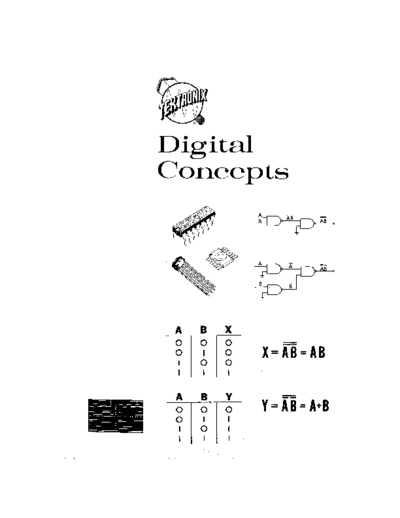
NAND GATE i s w r i t t e n as Y = E. By DeMorgan's theorem
(3.13) t h i s e x p r e s s i o n c a n a l s o be w r i t t e n as
Y = + 3. Note t h a t i n one form of t h e e q u a t i o n ,
t h e AND f u n c t i o n i s i n d i c a t e d , i n t h e o t h e r form of
t h e e q u a t i o n t h e OR f u n c t i o n i s i n d i c a t e d .
32
A B Z
Fig. 4-2. NOR functions.
F i g . 4 - 2 A shows a d i g i t a l l o g i c c i r c u i t u s i n g two
PNP t r a n s i s t o r s . I n n e g a t i v e l o g i c system when i n p u t s
A o r B a r e made t r u e , t h e b a s e of t h e a p p r o p r i a t e
t r a n s i s t o r i s pulled negative with respect t o t h e
e m i t t e r which t u r n s t h e t r a n s i s t o r on. A t r u t h t a b l e
f o r t h i s g a t e i s shown i n F i g . 4 - 2 B . Output Z i s
t r u e o n l y when b o t h t r a n s i s t o r s a r e n o t c o n d u c t i n g .
Both t r a n s i s t o r s a r e o f f o n l y when A and B a r e b o t h
f a l s e . This r e s u l t i s equivalent t o taking t h e output
of a n OR g a t e and n e g a t i n g i t . The c i r c u i t i s
t h e r e f o r e r e f e r r e d t o as a n e g a t e d OR g a t e o r NOR
NOR g a t e . The symbol o r a NOR g a t e i s shown i n F i g . 4-2C-
The b a s i c s h a p e of t h e g a t e i n d i c a t e s a n OR f u n c t i o n .
33
The p r e s e n c e of a c i r c l e a t t h e o u t p u t i n d i c a t e s
l o g i c i n v e r s i o n a t t h a t p o i n t . An e q u a t i o n f o r a
NOR g a t e i s Z = m. By DeMorgan's Theorem (3.12)
t h i s e x p r e s s i o n i s a l s o e q u i v a l e n t t o 2 = Ti B. Thus,
i n t h e NOR g a t e as i n t h e NAND g a t e b o t h OR and AND
f u n c t i o n s can b e implemented. N e i t h e r t h e NAND g a t e
n o r t h e NOR g a t e a r e r e s t r i c t e d t o two i n p u t
c o n f i g u r a t i o n s . NAND o r NOR g a t e I C ' s a r e a v a i l a b l e
w i t h up t o f i v e i n p u t s .
The q u e s t i o n i s f r e q u e n t l y asked as t o why most
commercially a v a i l a b l e d i g i t a l i n t e g r a t e d - c i r c u i t
g a t e s are of t h e NAND o r NOR v a r i e t y . The answer i s
NAND or found by a p p l y i n g DeMorgan's theorem t o NAND and NOR
NOR as f u n c t i o n s . A s mentioned p r e v i o u s l y DeMorgan's theorem
AND or shows t h a t i n e i t h e r t h e NOR o r t h e NAND g a t e , both
OR AND and OR f u n c t i o n s are◦ Jabse Service Manual Search 2026 ◦ Jabse Pravopis ◦ onTap.bg ◦ Other service manual resources online : Fixya ◦ eServiceinfo