Service Manuals, User Guides, Schematic Diagrams or docs for : oki Printers LED 10i 10i_mm
<< Back | HomeMost service manuals and schematics are PDF files, so You will need Adobre Acrobat Reader to view : Acrobat Download Some of the files are DjVu format. Readers and resources available here : DjVu Resources
For the compressed files, most common are zip and rar. Please, extract files with Your favorite compression software ( WinZip, WinRAR ... ) before viewing. If a document has multiple parts, You should download all, before extracting.
Good luck. Repair on Your own risk. Make sure You know what You are doing.
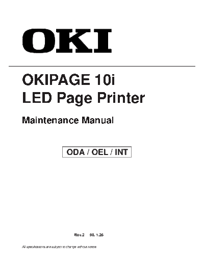
Image preview - the first page of the document

>> Download 10i_mm documenatation <<
Text preview - extract from the document
OKIPAGE 10i
LED Page Printer
Maintenance Manual


                                 ODA / OEL / INT


                                       Rev.2      98. 1.26


All specifications are subject to change without notice.
1.    CONFIGURATION

1.1   System Configuration

      OKIPAGE 10i consists of control and engine blocks in the standard configuration, as shown in
      Figure 1-1.

      In addition, the options marked with asterisk(*) are available.


                                                1-1
                  Operator Panel
                                                                      Engine Unit
   Paper
  Cassette                                                                            Face Up
                                                                                      Stacker
*High Capacity
Second Paper             Paper Feeding Mechanism
    Feeder                    (First Tray Unit)                       Face

*Multi Purpose                                                        Down
   Feeder
                             Electrophotographic                     Stacker
                               Processing Unit


                                                          Power Supply
                                                        and Sensor Board


  Centronics
                                   Main Control Board


                                   Memory*                                      * : Optional
                                Expansion Board
                              1 DRAM SIMM Socket
                              1 ROM SIMM Socket
                                                                 DRAM SIMM*

                                        or

   RS-232C                       RS-232C Serial*
                                 Interface Board
                              1 DRAM SIMM Socket
                              1 ROM SIMM Socket                  PS SIMM*
                                                                 (Post Script Program)
                                        or
                                                                           or
        LAN                          Network*
    (to BASE-T)                  Interface Board
                                                                 Flash SIMM*
                              1 DRAM SIMM Socket
                                                                 (Flash memory)
                               1 ROM SIMM Socket


                                         Figure 1-1


                                             1-2
1.2   Printer Configuration

      The printer unit consists of the following hardware components:
◦ Jabse Service Manual Search 2024 ◦ Jabse Pravopis ◦ onTap.bg ◦ Other service manual resources online : Fixya ◦ eServiceinfo