Service Manuals, User Guides, Schematic Diagrams or docs for : clarion DB-538 clarion_db538rmp_107
<< Back | HomeMost service manuals and schematics are PDF files, so You will need Adobre Acrobat Reader to view : Acrobat Download Some of the files are DjVu format. Readers and resources available here : DjVu Resources
For the compressed files, most common are zip and rar. Please, extract files with Your favorite compression software ( WinZip, WinRAR ... ) before viewing. If a document has multiple parts, You should download all, before extracting.
Good luck. Repair on Your own risk. Make sure You know what You are doing.
Image preview - the first page of the document
>> Download clarion_db538rmp_107 documenatation <<
Text preview - extract from the document
Clarion ( Malaysia) Sdn. Bhd.
Phase 3, Free Trade Zone One, 11900 Bayan Lepas, Penang, Malaysia
Published by Clarion (Malaysia)
Tel: (60) 4-6439-106, Fax: (60) 4-6439-108 289-6029-00 JUNE. 2003P
Clarion Co. Ltd. Printed In Malaysia
Export Division : 50 Kamitoda, Toda-shi, Saitama 335-8511 Japan
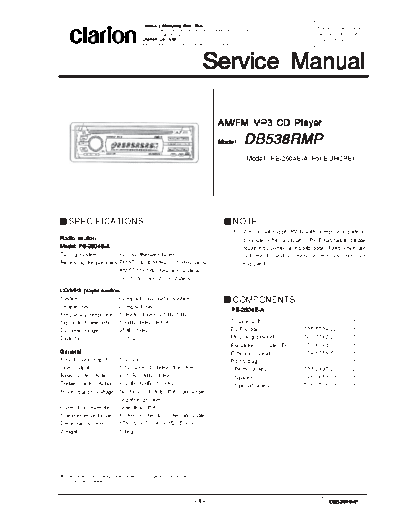
Service Manual
AM/FM MP3 CD Player
Model DB538RMP
(Model : PE-2604E-A: For EUROPE)
SPECIFICATIONS NOTE
1. We cannot supply PWB with component parts in
Radio section principle. When a circuit on PWB has failure, please
Model: PE-2604E-A repair it by component parts base. Parts which are
Tuning system: PLL synthesizer tuner not mentioned in service manual are not
Receiving frequencies:FM 87.0 to 108MHz (0.05 MHz steps) supplied.
AM 531 to 1,602kHz (9 kHz steps)
LW 153 to 279kHz (3 kHz steps)
CD/MP3 player section
System: Compact disc audio system COMPONENTS
Usable disc: Compact disc
PE-2604E-A
Frequency response: 10Hz to 20kHz (+1dB/-1dB)
Signal to Noise ratio: 100dB (1kHz) IHF-A Source unit 1
Dynamic range: 95dB (1kHz) DCP Case 335-5734-22 1
Distortion: 0.01% Mounting bracket 300-7742-20 1
Escutcheon (Outer-Es) 370-6041-00 1
General Extension Lead 854-6358-50 1
Max. Power Output: 50W x 4 Part's bag 1
Line Output: 1.7V (with CD 1kHz, 10k ohm) Removal key 331-2497-20 2
Bass Control Action: +13dB/-13dB (30Hz) Spacer 345-3653-01 1
Treble Control Action:
+12dB/-12dB (10 kHz) Special Screw 716-0726-01 1
Power supply voltage:DC 14.4V (10.8 to 15.6V allowable)
negative ground
Current consumption: Less than 15A
Speaker impedance: 4 ohm (4 ohm to 8 ohm allowable)
Dimensions (mm): 178 (W) x 50 (H) x 152 (D)mm
Weight: 1.1kg
Specification and design are subject to change without notice for
further improvement.
-1- DB538RMP
To engineers in charge of repair or that the laser optical diode lights up, keep your eyes
more than 30cms away from the lens. Prolonged
inspection of our products. viewing of the laser within 30cms may damage your
eyesight.
Before repair or inspection,make sure to follow the 9. Cautions in handling the optical pickup
instructions so that customers and Engineers in charge of The laser diode of the optical pickup can be damaged
repair or inspection can avoid suffering any risk or injury. by electrostatic charge caused by your clothes and body.
Make sure to avoid electrostatic charges on your clothes
1. Use specified parts. or body, or discharge static electricity before handling
The system uses parts with special safety features the optical pickup.
against fire and voltage. Use only parts with equivalent 9-1.Laser diode
characteristics when replacing them. The laser diode terminals are shorted for transportation
The use of unspecified parts shall be regarded as re- in order to prevent electrostatic damage. After
modeling for which we shall not be liable.The onus of replacement, open the shorted circuit. When removing
product liability (PL) shall not be our responsibility in the pickup from the mechanism, short the terminals by
cases where an accident or failure is as a result of soldering them to prevent this damage.
unspecified parts being used. 9-2.Actuator
2. Place the parts and wiring back in their original The actuator has a powerful magnetic circuit. If a
positions after replacement or re-wiring. magnetic material is put close to it. Its characteristics
For proper circuit construction, use of insulation tubes, will change. Ensure that no foreign substances enter
bonding, gaps to PWB, etc, is involved. The wiring con- through the ventilation slots in the cover.
nection and routing to the PWB are specially planned 9-3.Cleaning the lens
using clamps to keep away from heated and high volt- Dust on the optical lens affects performance. To clean
age parts. Ensure that they are placed back in their the lens, apply a small amount of isopropyl alcohol to
original positions after repair or inspection. lens paper and wipe the lens gently.
If extended damage is caused due to negligence dur-
ing repair, the legal responsibility shall be with the re-
pairing company. CAUTIONS
3. Check for safety after repair. The appliance contains a laser system and is classified as
Check that the screws, parts and wires are put back a "CLASS 1 LASER PRODUCT" . In case of any trouble
securely in their original position after repair. Ensure with this player, please contact your nearest "authorized
for safety reasons there is no possibility of secondary service station". To prevent direct exposure to the laser
problems around the repaired spots. beam, do not try to open the enclosure.
If extended damage is caused due to negligence of re-
pair, the legal responsibility shall be with the repairing
company.
4. Caution in removal and making wiring connection to
the parts for the automobile.
Disconnect the battery terminal after turning the igni-
tion key off. If wrong wiring connections are made with
the battery connected, a short circuit and/or fire may
occur. If extensive damage is caused due to negligence
of repair, the legal responsibility shall be with the repair-
ing company.
5. Cautions regarding chips.
Do not reuse removed chips even when no abnormal-
ity is observed in their appearance. Always replace them
with new ones. (The chip parts include resistors, ca-
pacitors, diodes, transistors, etc). The negative pole of
tantalum capacitors is highly susceptible to heat, so
use special care when replacing them and check the
operation afterwards.
6. Cautions in handling flexible PWB.
Before working with a soldering iron, make sure that the
iron tip temperature is around 270-C. Take care not to
apply the iron tip repeatedly (more than three times) to the
same patterns. Also take care not to apply the tip with
force.
7. Turn the unit OFF during disassembly and parts replace-
ment. Recheck all work before you apply power to the Bottom View of
unit. Main Unit
8. Cautions in checking that the optical pickup lights up.
The laser is focused on the disc reflection surface
through the lens of the optical pickup. When checking
DB538RMP -2-
TROUBLESHOOTING
Problem Cause Measure
Power does not turn on. Fuse is blown. Replace with a fuse of the same amperage. If the
(No sound is produced). fuse blows again, consult your store of purchase.
Incorrect wiring Consul your store of purchase.
Compact disc cannot be Another compact disc is already Eject the compact disc before loading the new
loaded. loaded. one.
Compact disc is dirty. Clean the compact disc with a soft cloth.
Sound skips or is noisy. Compact disc is heavily scratched Replace with a compact disc with no scratches.
or warped.
Sound is bad directly after Water droplets may form on the Let dry for about 1 hour with the power on.
power is turned on. internal lens when the car is
parked in a humid place.
Nothing happens when button Microprocessor has Turn off the power, then press the [RELEASE]
are pressed. malfunctioned due to noise, etc. button and remove the DCP.
Display is not accurate. Press the reset button for about 2 seconds with a
thin rod.
DCP or main unit connectors are Wipe the dirt off with a soft cloth moistened with
dirty. cleaning alcohol.
ADJUSTMENT
Item Procedure Measuring Instrument
S-Meter 1. Input the 98.1MHz/30dB u SG
(400Hz-MOD 30%) signal.
2. Turn on the power switch.
And press the AF button
and CH6 button at the
same time. (TEST MODE)
3. Adjust the reading of LCD
indicator to [24----00]
(2.4◦ Jabse Service Manual Search 2026 ◦ Jabse Pravopis ◦ onTap.bg ◦ Other service manual resources online : Fixya ◦ eServiceinfo