Service Manuals, User Guides, Schematic Diagrams or docs for : epson printer Epson EPL-N1200 Service Manual
<< Back | HomeMost service manuals and schematics are PDF files, so You will need Adobre Acrobat Reader to view : Acrobat Download Some of the files are DjVu format. Readers and resources available here : DjVu Resources
For the compressed files, most common are zip and rar. Please, extract files with Your favorite compression software ( WinZip, WinRAR ... ) before viewing. If a document has multiple parts, You should download all, before extracting.
Good luck. Repair on Your own risk. Make sure You know what You are doing.
Image preview - the first page of the document
>> Download Epson EPL-N1200 Service Manual documenatation <<
Text preview - extract from the document
EPSON TERMINAL PRINTER
EPL-N1200
SERVICE MANUAL
EPSON
4006838
All rights reserved. Reproduction of any part of this manual in any form whatsoever without
SEIKO EPSON's express written permission is forbidden.
The contents of this manual are subjects to change without notice.
All efforts have been made to ensure the accuracy of the contents of this manual. However, should
any errors be detected, SEIKO EPSON would greatly appreciate being informed of them.
The above notwithstanding SEIKO EPSON can assume no responsibility for any errors in this
manual or the consequence thereof.
Epson is a registered trademark of Seiko Epson Corporation.
General Notice: Other product names used herein are for identication purposes only and may be
trademarks of their respective campanies.
Copyright 0 1996 by SEIKO EPSON CORPORA T/ON Nagano, Japan
_i-
PRECAUTIONS
Precautionary notations throughout the text are categorized relative to 1) personal injury and 2)
damage to equipment.
DANGER Signals a precaution which, if ignored, could result in serious or fatal personal injury.
Great caution should be exercised in performing procedures preceded by DANGER
Headings.
WARfVlNG Signals a precaution which, if ignored, could result in damage to equipment.
The precautionary measures itemized below should always be observed when performing repair/
maintenance procedures.
DANGER
ALWAYS DISCONNECT THE PRODUCT FROM BOTH THE POWER SOURCE AND PERIPH-
ERAL DEVICES PERFORMING ANY MAINTENANCE OR REPAIR PROCEDURE.
NO WORK SHOULD BE PERFORMED ON THE UNIT BY PERSONS UNFAMILIAR WlTH
BASIC SAFETY MEASURES AS DICTATED FOR ALL ELECTRONICS TECHNICIANS IN
THEIR LINE OF WORK.
WHEN PERFORMING TESTING AS DICTATED WITHIN THIS MANUAL, DO NOT CON-
NECT THE UNIT TO A POWER SOURCE UNTIL INSTRUCTED TO DO SO. WHEN THE
POWER SUPPLY CABLE MUST BE CONNECTED, USE EXTREME CAUTION IN WORKING
ON POWER SUPPLY AND OTHER ELECTRONIC COMPONENTS.
WA FINING
1. REPAIRS ON EPSON PRODUCT SHOULD BE PERFORMED ONLY BY AN EPSON CERTIFIED
REPAIR TECHNICIAN.
2. MARE CERTAIN THAT THE SOURCE VOLTAGE IS THE SAME AS THE RATED VOLTAGE,
LISTED ON THE SERIAL NUMBER/RATING PLATE. IF THE EPSON PRODUCT HAS A
PRIMARY AC RATING DIFFERENT FROM AVAILABLE POWER SOURCE, DO NOT CON-
NECT IT TO THE POWER SOURCE.
3. ALWAYS VERIFY THAT THE EPSON PRODUCT HAS BEEN DISCONNECTED FROM THE
POWER SOURCE BEFORE REMOVING OR REPLACING PRINTED CIRCUIT BOARDS
AND/OR INDMDUAL CHIPS.
4. IN ORDER TO PROTECT SENSITIVE MICROPROCESSORS AND CIRCUITRY, USE STATIC
DISCHARGE EQUIPMENT, SUCH AS ANTI-STATIC WRIST STRAPS, WHEN ACCESSING
INTERNAL COMPONENTS.
5. REPLACE MALFUNCTIONING COMPONENTS ONLY WITH THOSE COMPONENTS BY
THE MANUFACTURE; INTRODUCTION OF SECOND-SOURCE ICs OR OTHER NONAP-
PROVED COMPONENTS MAY DAMAGE THE PRODUCT AND VOID ANY APPLICABLE
EPSON WARRANTY.
SAFETY INFORMATION
This printer is a page printer which operates by means of a laser. There is no possibility of danger from
the laser, provided the printer is operated according to the instructions in this manual provided.
Since radiation emitted by the laser is completely confined within protective housings, the laser beam
cannot escape from the machine during any phase of user operation.
For United States Users;
[Laser Safety]
This printer is certified as a Class 1 Laser product under the U.S. Department of Health
and Human Services (DHHS) Radiation Performance Standard according to the Radia-
tion Control for Health and Safety Act of 1968. This means that the printer does not
produce hazardous laser radiation.
ICDRH Regulations]
The Center for Devices and Radiological Health (CDRH) of the U.S. Food and Drug
Administration implemented regulations for laser products on August 2,1976. Compli-
ance is mandatory for products marketed in the United States. The label shown below
indicates compliance with the CDRH regulations and must be attached to laser products
marketed in the United States.
WARNING : Use of controls, adjustments or performance of procedures other
than those specified in this manual may result in hazardous radiation exposure.
[Internal Laser Radiation]
Maximum Radiation Power: 5.0x lO-QW)
Wave Length: 790 f20nm
This is a Class IIIb Laser Diode Assay that has an invisible laser beam. The print head
unit is NOT A FIELD SERVICE ITEM. Therefore, the print head unit should not be
opened under any circumstances.
For Other Countries Users;
WARNING: Use of controls, adjustments or performance of procedures other
than those specified in this manual may result in hazardous radiation exposure.
I This is a semiconductor laser. The maximum power of the laser diode is 5.0
lo4 W and the wavelength is 790 + 20 nm. 1
For Denmark Users;
ADVARSEL
Usynlig laserstr&ling ved Abning, r&r sikkerhedsafbrydere er ude af funktion
Undga udsaettelse for strtig.
1 Klasse 1 laser nrodukt der onfvlder IEC825 sikkerheds kravene. I
...
- III -
For Finland. Sweden Users:
vARoITus
Laitteen kayttaminen muulla kuin t&&i kayttoohjeessa mainitulla tavalla saat-
taa altistaa kayttajan turvallisuusluokan 1 ylittaville nakymatt6mHlle
lasersateiylle.
VARNING
Om apparaten anvands pa at-mat sHtt an i denna bruksanvisning specificerats
kan anvandaren utsattas for osynlig laserstr&ing, som over&rider gr%ns
for laser klass 1.
For Finland, Sweden Service People
vARoITus
Avattaessa ja suojalukitus ohitettaessa olet alttiina nakymhttomalle laser
sateilylle. Ala katso sateeseen.
VARNING
Osynlig laserstr&lning nar denna de1 3r oppnad och spirren Hr urkopplad
Betrakta ei strblen.
For Norway Users;
1 ADVARSEL
Dersom apparatet brukes pa annen mate enn spesifisert i denne bruksan
visning, kan brukeren utsettes for unsynlig laserstr%ng som over&rider gren
sen for laser klasse 1.
Dette er en halvleder laser. Maksimal effeckt til laserdiode er 5.0 x lo4 W o
[bolgelengde er 790 f 20 run. I
Laser Safety Labels
[Label on rear printer case]
A laser safety labels is attached on the outside of the printer shown below.
For United State
This laser product conforms to the applicable
requirement of 21 CFR
Chapter I, subchapter J.
SEIKO EPSON CORP.
Hirooka Office
80 Hirooka, Shiojiri-shi, Nagano-ken,
Japan
MANUFACTURED:
- iv -
For Europe
[Label inside printer]
The following laser safely label will be attached inside the printer as shown below.
For Denmark, Finland, Sweden, and Norway
This manual describes functions, theory of electrical and mechanical operations, maintenance, and repair
of EPL-NlZOO.
The instructions and procedures included herein are intended for the experience repair technician, and
attention should be given to the precautions on the preceding page. The chapters are organized as
follows:
CHAPTER 1. GENERAL DESCRIPTION
Provides a general product overview, lists specifications, and illustrates the main components of the printer.
CHAPTER 2. OPERATING PRINCIPLES
Describes the theory of printer operation.
CHAPTER 3. DISASSEMBLY AND ASSEMBLY
Includes a step-by-step guide for product disassembly and assembly.
CHAPTER 4. ADJUSTMENTS
Includes a step-by-step guide for adjustment.
CHAPTER 5. TROUBLESHOOTING
Provides Epson-approved techniques for adjustment.
CHAPTER 6. MAINTENANCE
Describes preventive maintenance techniques and lists lubricants and adhesives required to service the equipment.
APPENDIX
Describes connector pin assignments, circuit diagrams, circuit board component layout and exploded diagram.
The contents of this manual are subject to change without notice.
- vi -
REVISION SHEET
I Revision I Issue Date Revision Page
Rev. A December 9 1996 1st issue
- vii -
TABLE OF CONTENTS
CHAPTER 1. GENERAL DESCRIPTION
CHAPTER 2. OPERATING PRINCIPLES
CHAPTER 3. DISASSEMBLY AND ASSEMBLY
CHAPTER 4. ADJUSTMENTS
CHAPTER 5. TROUBLESHOOTING
CHAPTER 6. MAINTENANCE
APPENDIX
...
- VIII -
Chapter 1 General Description
Table of Contents
1.1 FEATURES 1-1
1.2 SPECIFICATIONS 1-3
1.2.1 Basic Specifications . . . . . . . . . . . . . . . . . . . . . . . . . . . . . . . . . . . . . . . . . . 1-3
1.2.2 Electrical Specifications . . . . . . . . . . . . . . . . . . . . . . . . . . . . . . . . . . . . . . . 1-5
1.2.3 Reliability Specifications . . . . . . . . . . . . . . . . . . . . . . . . . . . . . . . . . . . . . . . 1-5
1.2.4 Environmental Conditions for Operating (Including Imaging Cartridge). . . 1-5
1.2.5 Environmental Condifitons for Storage and Transporation
(Excluding Image Cartridge). . . . . . . . . . . . . . . . . . . . . . . . . . . . . . . . . . . . 1-5
1.2.6 Applicable Standards (without any electrical optional unit) . . . . . . . . . . . . 1-6
1.2.7 Specification for Consumable (Imaging Cartridge) . . . . . . . . . . . . . . . . . . 1-6
1.2.8 Physical Specifications . . . . . . . . . . . . . . . . . . . . . . . . . . . . . . . . . . . . . . . . 1-6
1.2.9 Software Specifications . . . . . . . . . . . . . . . . . . . . . . . . . . . . . . . . . . . . . . . 1-7
1.2.10 Lower Paper Cassette (Option) Specifications . . . . . . . . . . . . . . . . . . . 1-11
1.3 INTERFACE SPECIFICATIONS 1-12
1.3.1 Parallel Interfaces. . . . . . . . . . . . . . . . . . . . . . . . . . . . . . . . . . . . . . . . . . . 1-12
1.3.1.1 Compatibility (Standard) Mode . . . . . . . . . . . . . . . . . . . . . . . . . . 1-12
1.3.1.2 Nibble (Reverse), ECP Mode . . . . . . . . . . . . . . . . . . . . . . . . . . . 1-14
1.3.2 Optional Serial Interface (LocalTalk/Serial Module). . . . . . . . . . . . . . . . . 1-18
1.4 OPERATING INSTRUCTIONS 1-22
1.4.1 Control Panel . . . . . . . . . . . . . . . . . . . . . . . . . . . . . . . . . . . . . . . . . . . . . . 1-22
1.4.2 SelecType Functions . . . . . . . . . . . . . . . . . . . . . . . . . . . . . . . . . . . . . . . . 1-24
1.4.3 Service Mode . . . . . . . . . . . . . . . . . . . . . . . . . . . . . . . . . . . . . . . . . . . . . . 1-29
1.4.3.1 Hexadecimal Dump Mode . . . . . . . . . . . . . . . . . . . . . . . . . . . . . . 1-29
1.4.3.2 EEPROM Format. . . . . . . . . . . . . . . . . . . . . . . . . . . . . . . . . . . . . 1-29
1.4.3.3 Error Recovery. . . . . . . . . . . . . . . . . . . . . . . . . . . . . . . . . . . . . . . 1-30
1.4.4 Display of Messages . . . . . . . . . . . . . . . . . . . . . . . . . . . . . . . . . . . . . . . . 1-31
1.4.4.1 Status Messages . . . . . . . . . . . . . . . . . . . . . . . . . . . . . . . . . . . . . 1-31
1.4.4.2 Error Messages . . . . . . . . . . . . . . . . . . . . . . . . . . . . . . . . . . . . . 1-32
1.4.4.3 Warning Message . . . . . . . . . . . . . . . . . . . . . . . . . . . . . . . . . . . . 1-33
1.4.5 Multi-User and Multi-Emulation . . . . . . . . . . . . . . . . . . . . . . . . . . . . . . . . 1-34
1.4.6 Emulation Mode Switch Function . . . . . . . . . . . . . . . . . . . . . . . . . . . . . . . 1-35
1.4.6.1 Emulation Switch by SPL. . . . . . . . . . . . . . . . . . . . . . . . . . . . . . . 1-35
1.4.6.2 Intelligent Emulation Switch. . . . . . . . . . . . . . . . . . . . . . . . . . . . . 1-35
1.4.7 Bi Resolution Improvement Technology . . . . . . . . . . . . . . . . . . . . . . . . . 1-36
1.4.8 Printer Initialization . . . . . . . . . . . . . . . . . . . . . . . . . . . . . . . . . . . . . . . . . . 1-37
1.4.9 Toner Save Mode . . . . . . . . . . . . . . . . . . . . . . . . . . . . . . . . . . . . . . . . . . . 1-38
1.5 MAIN COMPONENTS 1-39
1.5.1 C205 MAIN Board . . . . . . . . . . . . . . . . . . . . . . . . . . . . . . . . . . . . . . . . . . 1-40
1.5.2 C173 PROG Board`. . . . . . . . . . . . . . . . . . . . . . . . . . . . . . . . . . . . . . . . . 1-41
1.5.3 Control Panel. . . . . . . . . . . . . . . . . . . . . . . . . . . . . . . . . . . . . . . . . . . . . . 1-41
1.5.4 Engine Coontroller Board . . . . . . . . . . . . . . . . . . . . . . . . . . . . . . . . . . . . 1-42
1.5.5 Power Supply Board . . . . . . . . . . . . . . . . . . . . . . . . . . . . . . . . . . . . . . . . 1-42
1.5.6 High-Voltage Supply Board . . . . . . . . . . . . . . . . . . . . . . . . . . . . . . . . . . . 1-43
1.5.7 Optical Unit . . . . . . . . . . . . . . . . . . . . . . . . . . . . . . . . . . . . . . . . . . . . . . . 1-43
1.5.8 Fusing Unit . . . . . . . . . . . . . . . . . . . . . . . . . . . . . . . . . . . . . . . . . . . . . . . 1-44
1.5.9 Imaging Cartridge . . . . . . . . . . . . . . . . . . . . . . . . . . . . . . . . . . . . . . . . . . 1-44
1.5.10 Lower Paper Cassette. . . . . . . . . . . . . . . . . . . . . . . . . . . . . . . . . . . . . . 1-45
List of Figures
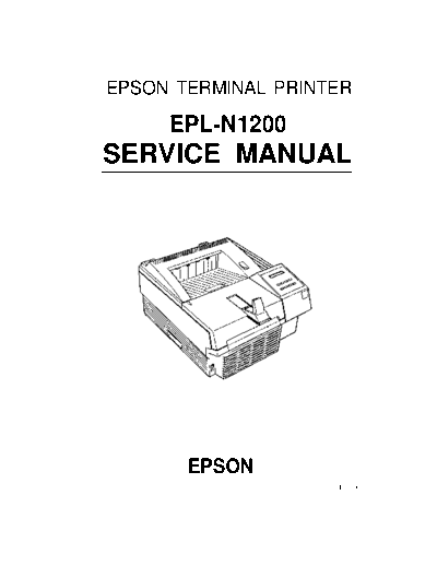
Figure 1-1. EPL-N1200 Exterior View . . . . . . . . . . . . . . . . . . . . . . . . . . . . . . . . 1-1
Figure 1-2. Printable Area . . . . . . . . . . . . . . . . . . . . . . . . . . . . . . . . . . . . . . . . . 1-4
Figure 1-3. Compatibility Mode Signal Timing . . . . . . . . . . . . . . . . . . . . . . . . . 1-12
Figure 1-4. Parallel Interface State Switch Diagram . . . . . . . . . . . . . . . . . . . . 1-15
Figure 1-5. Negotiation Timing Chart . . . . . . . . . . . . . . . . . . . . . . . . . . . . . . . 1-16
Figure 1-6. Data Transfer Timing Chart . . . . . . . . . . . . . . . . . . . . . . . . . . . . . . 1-16
Figure 1-7. Termination Timing Chart . . . . . . . . . . . . . . . . . . . . . . . . . . . . . . . 1-17
Figure 1-8. Interrupt Timing Chart . . . . . . . . . . . . . . . . . . . . . . . . . . . . . . . . . . 1-17
Figure 1-9. Control Panel . . . . . . . . . . . . . . . . . . . . . . . . . . . . . . . . . . . . . . . . . 1-22
Figure 1-10. Multi-Port and Multi-Emulation. . . . . . . . . . . . . . . . . . . . . . . . . . . 1-34
Figure 1-11. Emulation Switch by SPL. . . . . . . . . . . . . . . . . . . . . . . . . . . . . . . 1-35
Figure 1-12. Intelligent Emulation Switch . . . . . . . . . . . . . . . . . . . . . . . . . . . . . 1-35
Figure 1-13. BiRITech Effect . . . . . . . . . . . . . . . . . . . . . . . . . . . . . . . . . . . . . . 1-36
Figure 1-14. RITech Adjustment . . . . . . . . . . . . . . . . . . . . . . . . . . . . . . . . . . . 1-36
Figure 1-15. Toner Save Mode . . . . . . . . . . . . . . . . . . . . . . . . . . . . . . . . . . . . 1-38`
Figure 1-16. Component Layout. . . . . . . . . . . . . . . . . . . . . . . . . . . . . . . . . . . . 1-39
Figure 1-17. C205 Main Board . . . . . . . . . . . . . . . . . . . . . . . . . . . . . . . . . . . . . 1-40
Figure 1-18. C173 PROG Board . . . . . . . . . . . . . . . . . . . . . . . . . . . . . . . . . . . 1-41
Figure 1-19. Control Panel . . . . . . . . . . . . . . . . . . . . . . . . . . . . . . . . . . . . . . . . 1-41
Figure 1-20. Engine Controller Board. . . . . . . . . . . . . . . . . . . . . . . . . . . . . . . . 1-42
Figure 1-21. Power Supply Board . . . . . . . . . . . . . . . . . . . . . . . . . . . . . . . . . . 1-42
Figure 1-22. High-Voltage Supply Board . . . . . . . . . . . . . . . . . . . . . . . . . . . . . 1-43
Figure 1-23. Optical Unit . . . . . . . . . . . . . . . . . . . . . . . . . . . . . . . . . . . . . . . . . 1-43
Figure 1-24. Fusing Unit. . . . . . . . . . . . . . . . . . . . . . . . . . . . . . . . . . . . . . . . . . 1-44
Figure 1-25. Imaging Cartridge . . . . . . . . . . . . . . . . . . . . . . . . . . . . . . . . . . . . 1-44
Figure 1-26. Lower Paper Cassette . . . . . . . . . . . . . . . . . . . . . . . . . . . . . . . . . 1-45
List of Tables
Table 1-1. EPL-N1200 Options . . . . . . . . . . . . . . . . . . . . . . . . . . . . . . . . . . . . . . 1-2
Table 1-2. Paper Feed Methods . . . . . . . . . . . . . . . . . . . . . . . . . . . . . . . . . . . . . 1-3
Table 1-3. Paper Types . . . . . . . . . . . . . . . . . . . . . . . . . . . . . . . . . . . . . . . . . . . . 1-3
Table 1-4. Special Papers Usability . . . . . . . . . . . . . . . . . . . . . . . . . . . . . . . . . . 1-4
Table 1-5. Electrical Specifications . . . . . . . . . . . . . . . . . . . . . . . . . . . . . . . . . . . 1-5
Table 1-6. Differences between EPSON GL/2 and GL/2 in the
HP LaserJet 4 Emulation . . . . . . . . . . . . . . . . . . . . . . . . . . . . . . . . . . 1-7
Table 1-7. Built-in Fonts . . . . . . . . . . . . . . . . . . . . . . . . . . . . . . . . . . . . . . . . . . . 1-7
Table 1-8. Parallel Interface Pin Assignment . . . . . . . . . . . . . . . . . . . . . . . . . . 1-13
Table 1-9. Parallel Interface Pin Assignment . . . . . . . . . . . . . . . . . . . . . . . . . . 1-14
Table 1-10. Serial Interface Pin Assignments . . . . . . . . . . . . . . . . . . . . . . . . . . 1-19
Table 1-11. LocalTalk Interface Pin Assignments. . . . . . . . . . . . . . . . . . . . . . . 1-21
Table 1-12. SelecType Functions . . . . . . . . . . . . . . . . . . . . . . . . . . . . . . . . . . . 1-27
Table 1-13. Main Controller Board Default Paper Size Setting. . . . . . . . . . . . . 1-29
Table 1-14. Status Messages . . . . . . . . . . . . . . . . . . . . . . . . . . . . . . . . . . . . . . 1-31
Table 1-15. Error Messages . . . . . . . . . . . . . . . . . . . . . . . . . . . . . . . . . . . . . . . 1-32
Table 1-16. Warning Messages . . . . . . . . . . . . . . . . . . . . . . . . . . . . . . . . . . . . 1-33
Table 1-17. Differences in Components for the C205 MAIN Board . . . . . . . . . 1-40
EPL-N1200 Service Manual General Description
1.1 FEATURES
The EPSON◦ Jabse Service Manual Search 2026 ◦ Jabse Pravopis ◦ onTap.bg ◦ Other service manual resources online : Fixya ◦ eServiceinfo