Service Manuals, User Guides, Schematic Diagrams or docs for : panasonic Audio SA-PT570EB PSG0901003CE doc c9btgha2
<< Back | HomeMost service manuals and schematics are PDF files, so You will need Adobre Acrobat Reader to view : Acrobat Download Some of the files are DjVu format. Readers and resources available here : DjVu Resources
For the compressed files, most common are zip and rar. Please, extract files with Your favorite compression software ( WinZip, WinRAR ... ) before viewing. If a document has multiple parts, You should download all, before extracting.
Good luck. Repair on Your own risk. Make sure You know what You are doing.
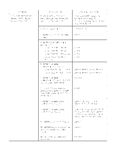
Image preview - the first page of the document

>> Download c9btgha2 documenatation <<
Text preview - extract from the document
        Problems                  Checking Points                   Checking components
1) TV does not have any   1) Check setting of the set in       * This year HDMI always ON.
display. Set FL display   Setup Menu whether the HDMI          No need check Setup Menu.
shows U702/U703           Video output is turned ON            If no resolution selection GUI, then
                                                               only check SETUP.

                          2) +5V Supply to the TV              IC3952 (Pin 4)


                          3) HDMI Connector Solderability      P3901
                          condition

                          4) HDMI Output TDMS signal
                          lines (IC3901)
                              - Data (TX0P/M => 14, 16)        L3905
                             - Data (TX1P/M => 18, 20)         L3904
                             - Data (TX2P/M => Pin 22, 24)     L3903
                             - Clock (TXCP/TXCM =>             L3906
                             Pin 10, 12)

                          5) HDMI Transmitter
                          communication lines to TV
                              - Data, SDA (Pin 120, IC3901)    LB3905, R3905, Q3902, R3904
                             - Clock, SCL (Pin 121, IC3901)    LB3904, R3907, Q3903, R3906

                          6) HDMI Transmitter                  RX3901
                          communication from LSI (IC8001)
                          (I2C_SCL/I2C_SDA signals)

                          7) Local Port Slave Address          R3921
                          setting resistor at Pin 99 of HDMI
                          Transmitter LSI IC (IC3901) for
                          LPSA signal

                          8) HDMI Transmitter LSI IC           LB3901, LB3902, IC3901
                          (IC3901) +3.3V Supply                (Pin 9, 13, 17, 21, 25, 124)

                          9) HDMI Transmitter LSI IC           IC3901 (Pin 5, 26, 42, 47, 55, 75,
                          (IC3901) +1.2V Supply                85, 102, 109, 116, 123), LB3908,
                                                               IC8151 (Pin 4), LB8001, IC8001
                                                               (Pin 20, 44, 83, 158, 187, 211)

                          10) HDMI Up-Con +3.3V Supply         LB3901

                          11) HDMI Pixel Clock Output from     LB8901
                          Up-Con to HDMI Transmitter
                          (VCLK)

                          12) Up-Con IC I2C Data and           RX3901
                          Clock Line
◦ Jabse Service Manual Search 2024 ◦ Jabse Pravopis ◦ onTap.bg ◦ Other service manual resources online : Fixya ◦ eServiceinfo