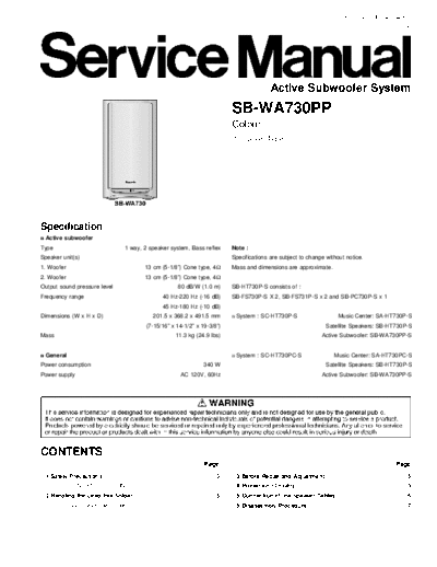
Service Manuals, User Guides, Schematic Diagrams or docs for : panasonic Audio SB-WA730 hfe_panasonic_sb-wa730pp_service
<< Back | HomeMost service manuals and schematics are PDF files, so You will need Adobre Acrobat Reader to view : Acrobat Download Some of the files are DjVu format. Readers and resources available here : DjVu Resources
For the compressed files, most common are zip and rar. Please, extract files with Your favorite compression software ( WinZip, WinRAR ... ) before viewing. If a document has multiple parts, You should download all, before extracting.
Good luck. Repair on Your own risk. Make sure You know what You are doing.
Image preview - the first page of the document

>> Download hfe_panasonic_sb-wa730pp_service documenatation <<
Text preview - extract from the document
                                                                                                                      ORDER NO. MD0411542C1
                                                                                                                                         A6


                                                                                           Active Subwoofer System
                                                                            SB-WA730PP
                                                                            Colour
                                                                            (S)...Silver Type


Specification
n Active subwoofer
Type                             1 way, 2 speaker system, Bass reflex       Note :
Speaker unit(s)                                                             Specifications are subject to change without notice.
1. Woofer                                  13 cm (5-1/8") Cone type, 4      Mass and dimensions are approximate.
2. Woofer                                  13 cm (5-1/8") Cone type, 4
Output sound pressure level                            80 dB/W (1.0 m)      SB-HT730P-S consists of :
Frequency range                                  40 Hz-220 Hz (-16 dB)      SB-FS730P-S X 2, SB-FS731P-S x 2 and SB-PC730P-S x 1
                                                 45 Hz-180 Hz (-10 dB)
Dimensions (W x H x D)                       201.5 x 368.2 x 491.5 mm       n System : SC-HT730P-S                    Music Center: SA-HT730P-S
                                           (7-15/16" x 14-1/2" x 19-3/8")                                        Satellite Speakers: SB-HT730P-S
Mass                                                  11.3 kg (24.9 lbs)                                       Active Subwoofer: SB-WA730PP-S


n General                                                                   n System : SC-HT730PC-S                 Music Center: SA-HT730PC-S
Power consumption                                                 340 W                                          Satellite Speakers: SB-HT730P-S
Power supply                                            AC 120V, 60Hz                                          Active Subwoofer: SB-WA730PP-S


CONTENTS
                                                                  Page                                                                    Page
 1 Safety Precautions                                                  3     3 Before Repair and Adjustment                                   5
       1.1. GENERAL GUIDELINES                                         3     4 Protection Circuitry                                           5
 2 Handling the Lead-free Solder                                       5     5 Connection of the Speaker Cables                               6
       2.1. About lead free solder (PbF)                               5     6 Disassembly Procedure                                          7
SB-WA730PP
              6.1. Disassembly flow chart                                 7       11 Printed Circuit Board                               22
              6.2. Disassembly of the Speaker Unit and Checking of the                11.1. Power P.C.B.                                 22
                  P.C.B.                                                  9           11.2. AC Inlet P.C.B. and Transformer P.C.B.       24
        7 Voltage Measurement and Waveform Chart                         15       12 Wiring Connection Diagram                           25
              7.1. Voltage Measurement                                   15       13 Illustration of IC   , Transistors and Diodes       26
              7.2. Waveform                                              16       14 Parts Location and Replacement Parts List           27
        8 Block Diagram                                                  17           14.1. Cabinet                                      28
        9 Notes of Schematic Diagram                                     18           14.2. Electrical Parts List                        31
       10 Schematic Diagram                                              19           14.3. Packing Materials & Accessories Parts List   33
             10.1. Power Circuit                                         19           14.4. Packaging                                    33
             10.2. Transformer Circuit and AC Inlet Circuit              21


                                                                              2
                                                                                                                                      SB-WA730PP


1 Safety Precautions
1.1.      GENERAL GUIDELINES
 1. When servicing, observe the original lead dress. If a short circuit is found, replace all parts which have been overheated or
    damaged by the short circuit.
 2. After servicing, ensure that all the protective devices such as insulation barriers, insulation papers shields are properly installed.
 3. After servicing, check for leakage current to prevent from being exposed to shock hazards.


(This "Safety Precaution" is applied only in U.S.A.)
 1. Before servicing, unplug the power cord to prevent an electric shock.
 2. When replacing parts, use only manufacturer's recommended components for safety.
 3. Check the condition of the power cord. Replace if wear or damage is evident.
 4. After servicing, be sure to restore the lead dress, insulation barriers, insulation papers, shields, etc.
 5. Before returning the serviced equipment to the customer, be sure to make the following insulation resistance test to prevent the
    customer from being exposed to a shock hazard.


1.1.1.      LEAKAGE CURRENT COLD CHECK
 1. Unplug the AC cord and connect a jumper between the two prongs on the plug.
 2. Using an ohmmeter measure the resistance value, between the jumpered AC plug and each exposed metallic cabinet part on
    the equipment such as screwheads, connectors, control shafts, etc. When the exposed metallic part has a return path to the
    chassis, the reading should be between 1M and 5.2.
    When the exposed metal does not have a return path to the chassis, the reading must be     .


                                                                  Fig. 1


1.1.2.      LEAKAGE CURRENT HOT CHECK (See Figure 1.)
 1. Plug the AC cord directly into the AC outlet. Do not use an isolation transformer for this check.
 2. Connect a 1.5k, 10 watts resistor, in parallel with a 0.15
◦ Jabse Service Manual Search 2024 ◦ Jabse Pravopis ◦ onTap.bg ◦ Other service manual resources online : Fixya ◦ eServiceinfo