Service Manuals, User Guides, Schematic Diagrams or docs for : panasonic Cam NV-GS6 NV-GS6EE disassem_nv

<< Back | Home

Most service manuals and schematics are PDF files, so You will need Adobre Acrobat Reader to view : Acrobat Download Some of the files are DjVu format. Readers and resources available here : DjVu Resources
For the compressed files, most common are zip and rar. Please, extract files with Your favorite compression software ( WinZip, WinRAR ... ) before viewing. If a document has multiple parts, You should download all, before extracting.
Good luck. Repair on Your own risk. Make sure You know what You are doing.


Image preview - the first page of the document
disassem_nv


>> Download disassem_nv documenatation <<

Text preview - extract from the document
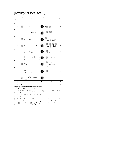
MAIN PARTS PORTION
STEP Ref.                         Section
                  PART                            REMOVE                 NOTE
No.  No.                          No.


  1     52   Top Unit               1       4 433, 541                    1


             Side Case R &                  2 450, 4 533 ,
  2     -
             LCD Ass'y              1       FP7, FP8                      2

                                             533 , FP11 or FP9
  3     12   EVF Unit               1       (For model with Color EVF)    3

                                            2 433, 450 , 533, 533
  4     11   Rear Case Unit         1       (For model with S-VIDEO)      4
                                            P1, (L-1)

  5     -    Lens Ass'y             1       2 533 , FP301,
                                                                          5
                                            FP701

  6     -    Front Case Ass'y &     1       3 433 , FP6, B1               6
             Bottom Case Ass'y
                                            2 450 , FP1,FP2,
  7     E10 Main C.B.A.             1       FP3, FP4, FP5,                7
                                            FP10

             Mechanism                      3 413
  8     -
             Chassis Ass'y          1                                     8


  9          Cassette Cover                 -----
        2
             Unit                   1                                     -


  A     B           C              D                    E                 F
How to read chart shown above:
A: Order of Procedure steps.
   When reassembling, perform steps(s) in reverse order.
B: Ref No.
C: Part to be removed or installed.
D: Section No.
E: Identification of part to be removed, unhooked, unlocked,
   released, unplugged, unclamped, or unsoldered.
    3 404 = 3 Screws 404 , 2(L-1) = 2 Looking Tabs (L-1)
F: Refer to "Notes in chart."
                                                                                                                   Note:
    1 MAIN PARTS SECTION                                                                                           1. Parts with no Ref. No. in "EXPLODED VIEW" are not supplied.
                                                                                                                      And some Ref. No. will be skipped. Be sure to make your
                                                                                                                      orders of replacement parts according to the parts list.
                                                                                                                   2. The parts indicated by the dotted line     are for Ass'y only
                                                                                                                      and are not supplied.
                                                                                                                   3. Disregard Ref. No. suffixes when ordering parts. They are used
                                                                                                                      to describe parts in "Disassembly/Assembly Procedures" section.
                                               433 -1
                                                                                                             Side Case R & LCD Ass'y                     533 -2
H                                                                  12                                                                                             533 -2
     (NV-GS17EG/EF/E/EP/EB, NV-GS18E,                                                                                                                                                        5
                                                                                           533 -3
      NV-GS21EG/EK/E/EP/EB,
      NV-GS25GC/GN, NV-GS28GK,
      NV-GS35EG/E/EP/EB/GC/GN, NV-GS38GK)
         533 -4


                                433 -4
G

                                  533 -4
                                                                                                                                                                                    433 -1

                       533 -2
                                  (L-1)
                                                                                                        450 -7
                      450 -4
F
                         433 -4                                                                                                                                            533 -5

                                                                            P1                    E10                                                                                 Lens Ass'y
                                                    11
                                                                  FP10            FP9 or               FP301
              Mechanism Chassis Ass'y                                             FP11                      FP701

                                                                                                       FP6
                                                                           FP4                   FP1
E                                                                                 FP2                  FP8
                                                                                           FP3                                         450 -7
                                                                                                                                                                                                   533 -5
                                                                                                                        FP7
                                                                                                                        B1
                                                                                                                                                            433 -1
                                                                                                                 FP5
                                                                                                                                                                              52

D


                                                         413 -8                                                                                               541 -1
C


          2
                                                         433 -6
                                                                         413 -8
                                                                                                                                                                                    433 -1


B                                                                            413 -8
                                                                                                                                                                                             533 -2


                                                                                                                        433 -6
A                                                                                                                                                         Front Case Ass'y & Bottom Case Ass'y
                                                                                      4                                       450 -2
                                                                                                                                            433 -6          450 -2

              1                            2                        3                                         4                                      5                                 6
FRONT & BOTTOM CASE PORTION

STEP Ref.                             Section
                    PART                                REMOVE       NOTE
No.  No.                              No.


  1     -    Bottom Case Ass'y          2       433 , 450             -

        E30 Jack C.B.A.                         450 , 2 541
  2
        -    Bottom Angle Ass'y
                                        2       2 541
                                                                      9


  A     B            C                 D                    E         F


STEP Ref.                             Section
                    PART                                REMOVE       NOTE
No.  No.                              No.


                                                4 533 ,
  1     E20 Front C.B.A.                2       Light Shield Sheet
                                                                      10

             (For model with Light)
  2     56
             Four Eyes Lens             2       -----                 10


  3     51   Front Case                 2       -----                 -


  A     B            C                 D                    E         F
How to read chart shown above:
A: Order of Procedure steps.
   When reassembling, perform steps(s) in reverse order.
B: Ref No.
C: Part to be removed or installed.
D: Section No.
E: Identification of part to be removed, unhooked, unlocked,
   released, unplugged, unclamped, or unsoldered.
   3 404 = 3 Screws 404 , 2(L-1) = 2 Looking Tabs (L-1)
F: Refer to "Notes in chart."
                                                                                                                                      Note:
    2 FRONT AND BOTTOM CASE SECTION                                                                                                   1. Parts with no Ref. No. in "EXPLODED VIEW" are not supplied.
                                                                                                                                         And some Ref. No. will be skipped. Be sure to make your
                                                                                                                                         orders of replacement parts according to the parts list.
                                                                                                                                      2. The parts indicated by the dotted line     are for Ass'y only
            533                                                                                                                          and are not supplied.
                                                                                                                                      3. Disregard Ref. No. suffixes when ordering parts. They are used
                                                                                                                                         to describe parts in "Disassembly/Assembly Procedures" section.
                                                                                                                E20
     533
                                                                        703
H
                                                                                           (NV-GS6GC,
       57                                                                                   NV-GS25GC/GN,                                                     56 (NV-GS21EG/EK/E/EP/EB,
                                                                                        704 NV-GS28GK,                                                                 NV-GS35EG/E/EP/EB/GC/GN,
                                                   701                                      NV-GS35EG/E/EP/EB/GC/GN,                                                   NV-GS38GK)
                                                                                            NV-GS38GK)


G                     533                                                                      705


                                                                                                                                                        51
                                                                                                                      702
                                                                                                                             708
                                                       533
                                 541

F
                                                             541
                                                                                                                                                                                                58
                                                                      (NV-GS21EG/EK/E/EP/EB,
                                                                   711 NV-GS25GC/GN,
                                                                       NV-GS28GK, NV-GS35EG/E/EP/EB,
                                                                       NV-GS35GC/GN, NV-GS38GK)


E
                                                                                                                            433

                                                                                                                                                                  60
                                                                                                                                                                                            9
                                                                                  E30
                                                                                                                                                                                  59
                                                                                                                                                                  542                                      10
                                                                                                                                                 542
D
                                       7
                                                                                                     77                73                  543
                                                                                                                             542                                       55
                                                                                                                                                        543                       54
                                                                              6
                                                                                                                                                                                                     53
                                            541                                                                                                                              75
                                                              541
C
                       Bottom Angle Ass'y
                                                                                                                                                                                                          543

                                                                                                                                                                                                 76


B
                                                                                                          450
                                                                                                                                                             71

                                                                                                                                                                        Bottom Case Ass'y
                                                  72
                                                                                        8
A
                                                                                                                                                       450


                  1                                      2                              3                                         4                           5                                 6
SIDE CASE R & LCD PORTION
STEP Ref.                        Section
                   PART                            REMOVE   NOTE
No.  No.                         No.


  1     31   Side Case R Unit      3       419 , 457         11


  2     33   LCD Case A Unit       3       2 455 , 8(L-1)    -

  3     32   Shaft Case Unit       3       FP8101            11


        E40 LCD Backlight                  542, (L-2),
  4
             C.B.A.                3       FP8102
                                                             12


  5     34   LCD Case B            3       4(L-3)            12


        -    LCD Panel Ass'y
  6                                3       3(L-4)            12
        35
             LCD Shield Case
             Unit


  A     B             C           D                    E     F


STEP Ref.                        Section
                   PART                            REMOVE   NOTE
No.  No.                         No.


  1     42   LCD Panel             3       -----             13


  2     39   Reflect Sheet         3       (L-5)             13

  3     37   Lead Light Panel      3       -----             13

  4     38   Diffusion Sheet       3       -----             13

  5     40   BEF Sheet             3       -----             13


  6     41   BEF Sheet A           3       -----             13


  7     36   Panel Holder Unit     3       -----             13


  A     B             C          D                     E     F
How to read chart shown above:
A: Order of Procedure steps.
   When reassembling, perform steps(s) in reverse order.
B: Ref No.
C: Part to be removed or installed.
D: Section No.
E: Identification of part to be removed, unhooked, unlocked,
   released, unplugged, unclamped, or unsoldered.
    3 404 = 3 Screws 404 , 2(L-1) = 2 Looking Tabs (L-1)
F: Refer to "Notes in chart."
                                                                         Note:
    3 SIDE CASE R AND LCD SECTION                                        1. Parts with no Ref. No. in "EXPLODED VIEW" are not supplied.
                                                                            And some Ref. No. will be skipped. Be sure to make your
                                                                            orders of replacement parts according to the parts list.
                                                                         2. The parts indicated by the dotted line     are for Ass'y only
                                                                            and are not supplied.
                                                                         3. Disregard Ref. No. suffixes when ordering parts. They are used
                                                                            to describe parts in "Disassembly/Assembly Procedures" section.
                                34


H


                                                  35


                                                                                                                    LCD Panel Ass'y
                                                                          42

G                                                                             (L-3)         36

                                A                                                            (L-4)           41
                                                                                 (L-5)                              40
              B                                                         (L-3)                                                  38
                                                                                                                                      37


F                                                                                                                                              39
                                                       (L-4)
                                                                                  (L-3)


                                                               (L-3)


                                     E40
E

                                     FP8101


                                                                                                                                      33
                                                                                                                    (L-1)
                  542                                                                                    (L-1)
                        (L-2)         FP8102
                                                                                          (L-1)                                        (L-1)
D

                                              A                                 419
                                                                                                                                       (L-1)


                                                                   32
             31                                                         455                                                   (L-1)
C                                                                                                                     (L-1)
                                                       B         457                                        (L-1)

                                                                        455


B


A


         1          2                  3                           4                                 5                                     6
CCD & LENS PORTION
STEP Ref.                                   Section
                     PART                                     REMOVE                NOTE
No.  No.                                    No.


  1     E50 CCD C.B.A.                        4       2 536                          14


  2     64   Filter Rubber                    4       -----                          14


  3     63   Optical Filter                   4       -----                          14

             (For model with 20,24X zoom)
  4     62
             Filter Holder                    4       -----                          14


  A     B              C                     D                    E                  F


STEP Ref.                                   Section
                     PART                                     REMOVE                NOTE
No.  No.                                    No.


  1     65   Zoom Motor Unit                  4       2 538 , Unsolder               15

                                                      2 538, 533
  2     66   Focus Motor Unit                 4       (For model with 30X zoom) ,    15
                                                      Unsolder


  A     B              C                     D                    E                  F
How to read chart shown above:
A: Order of Procedure steps.
   When reassembling, perform steps(s) in reverse order.
B: Ref No.
C: Part to be removed or installed.
D: Section No.
E: Identification of part to be removed, unhooked, unlocked,
   released, unplugged, unclamped, or unsoldered.
   3 404 = 3 Screws 404 , 2(L-1) = 2 Looking Tabs (L-1)
F: Refer to "Notes in chart."
                                                                                Note:
    4 CCD AND LENS SECTION                                                      1. Parts with no Ref. No. in "EXPLODED VIEW" are not supplied.
                                                                                   And some Ref. No. will be skipped. Be sure to make your
                                                                                   orders of replacement parts according to the parts list.
                                                                                2. The parts indicated by the dotted line     are for Ass'y only
                                                                                   and are not supplied.
                                                                                3. Disregard Ref. No. suffixes when ordering parts. They are used
                                                                                   to describe parts in "Disassembly/Assembly Procedures" section.
                                                                                LUBRICATION POINTS
                                                                                When the marked parts are replaced, apply the recommended lubricants
H
                                                                                or adhesive for better maintenance of the unit.
                                                                                 Mark    Kind of Lubricant            Availability                Part Number
                                                                                         Grease            Available from Factroy                LSUQ0050


                                                                       61

G


                                                                   Lubrication Points


F


                                         E50
                 536

      536                                                                                                                            538
                                                                                                                                                538
E                                               64

                                                                                                                                           66


                                                63
                                                                                                                      Solder
D     (NV-GS6EE/GC,
       NV-GS17EG/EF/E/EP/EB, NV-GS18E, 62
       NV-GS21EG/EK/E/EP/EB,
                                                                                                                                     533
       NV-GS25GC/GN, NV-GS28GK)
                                                                                                                               (NV-GS35EG/E/EP/EB,
                                                                                                                                NV-GS35GC/GN,
                                                                                                                                NV-GS38GK)

                                   538
C
                                          538
                                                                                                        Lubrication Points


                                                     Solder       65


B


A


             1                           2                    3                      4                          5                               6
EVF PORTION

STEP Ref.                      Section
                  PART                           REMOVE   NOTE
No.  No.                       No.


  1     16   EVF Slide Piece     5       2 450             16

        13   EVF Base Frame
  2                              5                         16
        15   EVF Earth Plate             2(L-1)

  3     14   EVF Spring          5       450 , (L-2)       17


  4     17   EVF F.P.C.          5       FP951             17


  A     B           C           D                 E        F


STEP Ref.                      Section
                  PART                           REMOVE   NOTE
No.  No.                       No.


  1     18   Eye Cap             5       2 524             18

  2     23   EVF Lens Unit       5       -----             19

  3     22   Eye Sight Lever     5       -----             19


  A     B           C           D                 E        F
How to read chart shown above:
A: Order of Procedure steps.
   When reassembling, perform steps(s) in reverse order.
B: Ref No.
C: Part to be removed or installed.
D: Section No.
E: Identification of part to be removed, unhooked, unlocked,
   released, unplugged, unclamped, or unsoldered.
    3 404 = 3 Screws 404 , 2(L-1) = 2 Looking Tabs (L-1)
F: Refer to "Notes in chart."
                                                               Note:
    5 EVF SECTION                                              1. Parts with no Ref. No. in "EXPLODED VIEW" are not supplied.
                                                                  And some Ref. No. will be skipped. Be sure to make your
                                                                  orders of replacement parts according to the parts list.
                                                               2. The parts indicated by the dotted line     are for Ass'y only
                                                                  and are not supplied.
                                                               3. Disregard Ref. No. suffixes when ordering parts. They are used
                                                                  to describe parts in "Disassembly/Assembly Procedures" section.


H


               18

G
                                     22


                                                                              EVF Case Ass'y

                                    23                                524

F                                                             21

                        20


                              524
                                                                                     (L-2)
E


                                                                 FP951                            14
                             17
                                                450       (not supplied)


D
                                                                                     15


                                                                             (L-1)
                                                                                                       450
C


                                                                                                        16


                                                                                          13
B
                                          450
                                                      16


A


        1           2                3                4                              5                         6
Notes in chart
1. Removal of Top Unit                                        2. Installation of Side Case R & LCD Ass'y
   1) Open the LCD and the Cassette Cover, then remove           1) Connect the LCD F.P.C. and Side R F.P.C. to the
      the 5 Screws (433, 541).                                      Connectors FP7 and FP8 so as not to damage the
   2) Slide to extend the EVF.                                      F.P.C.s.
   3) Pull and slide the Top Unit carefully.                     2) Secure Front Portion and Rear Portion, and tighten 6
                                                                    Screws (450, 533)
   Installation of Top Unit
   1) Slide to extend the EVF.                                          Side Case R
   2) Insert Portion A of the Top Unit, and slide firmly to
      install.
                                    Open Cassette Cover
            Top Unit


                                      Portion A
                Slide
                                                                            Shape the inside                FP8


                                                                                                         FP7


                                                  Slide
                                                  EVF

                                                                                                  Rear
                   Open LCD                                                                       Portion            533
                                                                       Front
                         Fig. D1
                                                               533     Portion


                                                                                                               450


                                                                                      450


                                                                                       Fig. D2
3. Installation of EVF Unit                                    5. Installation of Lens Ass'y
   1) Confirm that the EVF F.P.C. is hooked to the Hooking        Take care not to damage the motor leads.
      Portions on the Bottom.                                     Install the Lens Ass'y with the 2 Bosses and 2 Screws
   2) Install the EVF Unit while holding the EVF F.P.C. to        (533).
      avoid damage of the EVF F.P.C.
                                                                                                       Lens Ass'y

                        Hold EVF F.P.C.          EVF Unit


                                                                                                       Motor leads

           Hooking
           Portions


         FP9 (For model with Color EVF)                           Boss                                   Boss
         or
         FP11 (For model with Monochrome EVF)

                           Fig. D3

4. Installation of Rear Case Unit                                                  FP701      FP301
   1) Position connector leads so as not to cover Portion A.


                                                                                          Fig. D5
                             P1                         Rear
                                       Connector        Case   6. Removal of Front Case Ass'y & Bottom Ass'y
                                       leads            Unit      1) Disconnect the Front F.P.C. from the Connector FP6.
                                                                  2) Open the Cassette Cover and remove the 3 Screws
                                                                     (433).
                                                                  3) Remove both the Front Case Ass'y & Bottom Case
                                                                     Ass'y and continue to grasp them, while disconnecting
                                                                     the Connector B1.
                                                                                                             Cassette Cover
                      Portion A
                          Fig. D4-1

   2) Secure the Locking Tab (L-1) of the Rear Case Unit to
      install it.

                                                                                        FP6
                                      Rear Case Unit


                                                                                        Front F.P.C.

                                                (L-1)                              B1


                                                                 Front Case Ass'y & Bottom Case Ass'y

                                                                                          Fig. D6

                                                                  Alternative method:
                                                                  If necessary, the Front Case Ass'y can be removed at first.
                        533 (For model with S-VIDEO)
                          Fig. D4-2
7. Installation of Main C.B.A.                                     8. Installation of Mechanism Chassis Ass'y
   Take care not to damage the F.P.C.s.                               Take care not to damage the F.P.C.s.
   1) Connect the Zoom Switch F.P.C. to the Connector                 1) After installing the Mechanism Chassis Ass'y, confirm
      FP10 on the Main C.B.A.                                            the F.P.C.s are positioned as shown.
   2) Connect the F.P.C.s to the connectors on the Main
      C.B.A, verifying that the direction of the Flexible Cables
      is correct. Refer to "REMOVAL/INSTALLATION OF
      F.P.C. FROM NON ZIF (Zero Insertion Force)
      CONNECTOR."
   3) After installing the Main C.B.A., confirm the F.P.C.s are
      positioned as shown.
                Cylinder Sub Mechanism Capstan         Zoom
                F.P.C. F.P.C.          F.P.C.          Switch
                                                       F.P.C.

                                                                             Mechanism Chassis Ass'y

   Head
   Amp Mechanism
   F.P.C. F.P.C.
                                                                                           Fig. D8-1

                                                                      Replacement of Mechanism Chassis Ass'y
                                                                      When replacing the Main Chassis Ass'y or the Cylinder
                                                                      Unit, be sure to perform the Envelope Output Adjustment.
                                                                      Refer to "ENVELOPE OUTPUT ADJUSTMENT" in
                                                                      MECHANICAL ADJUSTMENT.
                            Fig. D7                                   Handling Caution of Mechanism Chassis Ass'y
                                                                      When servicing the Mechanism Chassis Ass'y without the
                                                                      Cassette Up Unit, do not handle the Sub Chassis of the
                                                                      Mechanism Chassis Ass'y.
                                                                                    Mechanism Chassis Ass'y
                                                                                    (without Cassette Up Unit)

                                                                     Sub Chassis


                                                                                                       Sub Chassis


                                                                           Sub Chassis


                                                                                          Fig. D8-2
9. Removal of Jack C.B.A. & Bottom Angle Ass'y                            11. Removal of Side Case R Unit
   1) Open the L Cover.                                                       Open and rotate the LCD to access the 2 Screws (419, 457)
   2) Remove the Screw (450) and release the Tripod Portion                   as shown below, then remove it.
      from the hole.
                                                                             Installation of Side Case R Unit
   Installation of Jack C.B.A. & Bottom Angle Ass'y                          When installing, note to the direction of the Shaft Case
   Insert both the Jack C.B.A. & Bottom Angle Ass'y into the                 Unit. Be sure to install the LCD (Ass'y) into the Side Case
   2 slots and secure the Tripod into the hole.                              R Unit with the LCD rotated as shown. Otherwise, the LCD
                                                                             open/close switch on the Side Case R Unit will be damaged.
                           450
Open L Cover
                                                                                                                         Side Case R Unit
                                                                           LCD open/close SW.
                                                                                                     419
                          slot
                                                                                                                                Rotate
       slot


                           hole


Jack C.B.A. &                                                                                      457
Bottom Angle Ass'y                                      Tripod
                                                                                                           LCD (Ass'y)      Rotate


                                 Fig. D9
                                                                                 Shaft Case Unit
10. Installation of Front C.B.A.
    1) Install the Four Eyes Lens (For model with Light) into
       the Front Case. Then, install the Front C.B.A. with 2
       bosses of the Four Eyes Lens and 2 Screws (533).
    2) Install the Light Shield Sheet with 2 Screws (533).

                                     533
    Light Shield Sheet
                                            boss (For model with Light)                                  Fig. D11
      Front Case
                                                Four Eyes Lens
                                                (For model with Light)

                    533                     boss (For model with Light)


  Front
  C.B.A.
                                                  533

              533


                                 Fig. D10
12. Installation of LCD Backlight C.B.A., LCD Panel Ass'y,
    LCD Shield Case Unit, LCD Case B
    Use extreme care regarding LEDs when handling the LCD
    Backlight C.B.A.
    Install in order shown below.
    1) Install the LCD Panel Ass'y onto the LCD Shield Case
        Unit with the 3 Locking Tabs (L-4) while carefully
        bending the LCD F.P.C. at it's base so as not to damage
        it.
    2) Install the LCD Shield Case into the LCD Case B with
        the 4 Locking Tabs (L-3).
    3) Install the LCD Backlight C.B.A. onto the LCD Panel
        Ass'y with the Locking Tab (L-2).
    4) Tighten the Screw (542) while keeping the LCD Backlight
        C.B.A. pressed toward the right. Then, connect the
        Connector FP8102.
        542                      LCD Backlight C.B.A.
                                            Press


                        FP8102
         (L-2)
                                             LCD Panel Ass'y
                                                      (L-4)
                      (L-3)
              (L-3)


                                                          (L-3)
                        Bend

              (L-4)
                                              (L-3)


                       LCD                               LCD
                                                         Shield
                       F.P.C.                            Case
                                                         Unit


                                           LCD Case B


 boss


                                Fig. D12
13. Installation of LCD Panel, Reflect Sheet, Lead Light
    Panel, Diffusion Sheet, BEF Sheet, BEF Sheet A, Panel
    Holder Unit
    a. When replacing the LCD Panel, the Diffusion Sheet,
       the BEF Sheet and the BEF Sheet A, make sure to
       remove the Protection Sheets.                               Reflect Sheet
       To distinguish Sheets from attached Protection                                                  adhesive
       Sheet:                                                                                          tape
                                                                    Lead Light Panel
       - A blue Protection Sheet is affixed to both faces of the
         Diffusion Sheet.
       - A yellow Protection Sheet is affixed to both faces of
         the BEF Sheet.
       - A transparent Protection Sheet is affixed to both
         faces of the BEF Sheet A.
         Protection Sheet                    Diffusion Sheet        Diffusion Sheet
         (blue)
                                                                                            (white)


         Protection Sheet                                                 BEF Sheet
         (yellow)                             BEF Sheet
                                                                                            (stripe)


                                                                       BEF Sheet A
         Protection Sheet                     BEF Sheet A
         (green)                                                                              (gray)

                                                                                                       slot
                                                                                    (L-5)
                                                                   Panel Holder Unit                            slot
   b. Use extreme care when handling the LCD Panel, the
      Reflect Sheet, the Lead Light Panel, the Diffusion                                View A                         hole
      Sheet, the BEF Sheet and the BEF Sheet A to avoid
      damage, dust, and spots (especially fingerprints, etc.)                                                 adhesive
                                                                          adhesive                            tape
   Install in order shown below.                                          tape         hole
   1) Install in order the BEF Sheet A, BEF Sheet and
       Diffusion Sheet while inserting the corners of each
       sheets into the slots of the Panel Holder Unit.                                                                 cross mark
   2) Install the Lead Light Panel while inserting the corners
       into the slots of the Panel Holder Unit.                                                            LCD Panel
   3) Align the Reflect Sheet with the edge of the Panel                                           cross mark
       Holder Unit, and install it using adhesive tape on the
       Reflect Sheet.

                                                                                    cross mark cross mark
                         Reflect Sheet                adhesive
                                                      tape

                                                                    hole of Panel                                  hole of Panel
                                                                    Holder Unit               View A               Holder Unit
                                                                                            Fig. D13-2


                                       Do not touch
                                       the surface of
   Panel Holder Unit                   Lead Light Panel.

                          Fig. D13-1

   4) Install the LCD Panel with adhesive tape so that the
      cross marks are positioned in the center of the holes in
      the Panel Holder Unit.
14. Removal of CCD C.B.A., Filter Rubber, Optical Filter,             16. Installation of EVF Slide Piece, EVF Base Frame
    Filter Holder                                                         1) Pass the EVF F.P.C. through the EVF Base Frame
    CAUTION:                                                                 hole.
    1) When removing the CCD C.B.A., take care that the                   2) Install the EVF Slide Pieces into the EVF Base Frame
        Optical Filter does not fall out.                                    from both sides.
    2) Use extreme caution when removing the CCD C.B.A.                   3) Slide the EVF Case Ass'y to the end so that the ribs are
        as it is easily damaged by static electricity. Use a Wrist           inserted into the holes of the EVF Slide Pieces.
        Strap while removing and installing.                              4) Locate the threaded holes, and tighten the 2 Screws
    3) Do not touch the CCD window surface.                                  (450).
    Installation of CCD C.B.A., Filter Rubber, Optical Filter,            5) After installing, confirm the EVF moves correctly.
    Filter Holder
    Install in order shown below.                                                  EVF Base Frame hole of EVF
    1) Install the Filter Holder (For model with 30X zoom)            EVF Case Ass'y      rib     Slide Piece
        correctly.
    2) Install the Optical Filter correctly.                                                                       hole
        Note: Make sure that no dust gets on the Optical Filter
        or in the Lens Unit. Clean the Optical Filter with lens
        cleaning paper dampened with lens cleaner if
        necessary.
    3) Install the Filter Rubber on the Optical Filter correctly as                                                       EVF F.P.C.
        shown below.
        Note: Make sure that no dust gets on the Filter                                               hole of EVF
                                                                           Slide               rib
        Rubber.                                                                                       Slide Piece
    4) Install the CCD C.B.A. into the Lens Unit. Then, tighten                               
        the 2 Screws (536).
        Note: Do not touch the Lens Surface. Clean the surface
        with lens cleaning paper dampened with lens cleaner
        if necessary.
                                                                                    (threaded hole) 450
15. Installation of Zoom Motor Unit/Focus Motor Unit
    Install the Zoom Motor Unit/Focus Motor Unit so that the
    Shaft of the Zoom Motor Unit/Focus Motor Unit is set in the
    Holder.
                                                                                              EVF Slide Piece
                                                                           EVF Base Frame
                             shaft

                                                                                              
  Zoom
  Motor                                                                                          Fig. D16
  Unit


                       holder


                                     Bosses
                                              Bosses

                                              holder


  Focus
  Motor
  Unit


                                        shaft

                            Fig. D15
17. Installation of EVF Spring, EVF F.P.C.
    1) Insert the EVF F.P.C. into the EVF Spring hole paying
       particular attention to the direction.
    2) Connect the EVF F.P.C. to Connector FP951.
    3) Insert the Locking Tab (L-2) at first, then fit the EVF
       Spring in the EVF Case and tighten the Screw (450).


                           (L-2)
            EVF Spring

                 hole
                                        FP951
   EVF F.P.C.


                                            EVF Case

                                  Fit


                          Fig. D17

18. Removal of Eye Cap
    Remove the Eye Cap after removing the 2 Screws (524).

19. Handling cautions of EVF Lens Unit
    Use extreme care when handling the EVF Lens Unit to
    avoid damage, dust, and spots (especially fingerprints,
    etc.)

   Installation of EVF Lens Unit, Eye Sight Lever
   1) Install the Eye Sight Lever into the EVF Case hole in the
      direction shown.
   2) Install the EVF Lens Unit into the EVF Case while
      grasping both sides of the springs with tweezers, etc.
   3) After installing, confirm the Eye Sight Lever and the
      EVF Lens Unit work together correctly.


                EVF Case
                                                hole

       EVF Lens Unit
       Bosses
                                           Eye Sight Lever
       Spring


                               Bosses

                         Spring

                  Tweezers
                        Fig. D19


◦ Jabse Service Manual Search 2026 ◦ Jabse PravopisonTap.bg ◦ Other service manual resources online : FixyaeServiceinfo