Service Manuals, User Guides, Schematic Diagrams or docs for : panasonic DVD-Video NV-VHD1BEUSVC EU NV-VHD1B SVC cy120101
<< Back | HomeMost service manuals and schematics are PDF files, so You will need Adobre Acrobat Reader to view : Acrobat Download Some of the files are DjVu format. Readers and resources available here : DjVu Resources
For the compressed files, most common are zip and rar. Please, extract files with Your favorite compression software ( WinZip, WinRAR ... ) before viewing. If a document has multiple parts, You should download all, before extracting.
Good luck. Repair on Your own risk. Make sure You know what You are doing.
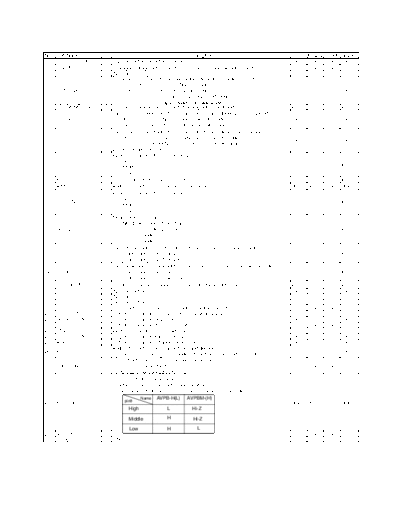
Image preview - the first page of the document
>> Download cy120101 documenatation <<
Text preview - extract from the document
No.   Port Name       I/O                                           Description                        P-OFF   P-Save P-FAIL Reset
1     CURRENT_LIMIT   O Capstan motor current limit terminal.                                          Low     Low    Low   Low
2     F ADJUST        O Analogue voltage output for HEAD frequency response adjustment                 Low     Low    Low   Low
3     N.C             -- (No Connection.)                                                              ---     ---    ---   ---
                         Terminal of the Current emphasis video/FM audio recording current.
                                [HIFI/2HEAD ]:Fix to Low (Normal mode)
4     C EMPHA(H)      O         [4HEAD]           :Fix to Low (factory mode)                           Low     Low    Low   Low
                                                    Fix to High (Insert/AV Insert mode)
                                                    Others (Depend on tape speed)
5     TRACKING_ENVE   O Playback envelope input for auto tracking adjustment and cvc.                  In      In     In    In
                         Tape running speed output terminal.(Output signal depens on tape speed)
6     SLP(H)          O       [High].........During NTSC_10H or PAL_9H mode                            Low     Low    Low   Low
                              [Low ].........Except NTSC_10H or PAL_9H mode
                         Tape running speed output terminal.(Output signal depens on tape speed)
                               [High].........During NTSC_4H/6H or PAL_6H/9H mode
7     LP(H)           O                                                                                Low     Low    Low   Low
                               [Low ].........Except NTSC_4H/6H or PAL_6H/9H mode
                         2HEAD model: Low Fix
                         Input terminal for "PB (H)" from AV2.
                               [High].........3.85V - 5.0V
8     CPB              I                                                                               In      In     In    In
                               [Midd].........1.82V - 2.84V
                               [Low ]......... 0V - 0.81V
9     AFC S            I "S-curve" Input terminal from tuner.                                          In      In     In    In
10    A-MUTE(H)       O Audio mute output terminal for RF Converter.                                   High    High   Low   High
                         Input terminal for "PB (H)" from AV1.
                               [High].........3.85V - 5.0V
11    AV1_8IN          I                                                                               In      In     In    In
                               [Midd].........1.82V - 2.84V
                               [Low ]......... 0V - 0.81V
                         Mode select terminal
                               [NORMAL mode ]: More than 4.0V
12    N/S/T2/T3        I       [SERVICE mode]: 2.5V - 4.0V                                             In      In     In    In
                               [TEST_2 mode ]: 1.0V - 2.5V
                               [TEST_3 mode ]: 0V - 1.0V
                         Tape end sensor input terminal.(Photo sensor input from supply side)
13    S-PHOTO          I       [Black Tape]: more than 2.6V                                            In      In     In    In
                               [Lead Tape]: Less than 2.4V
                         Tape beginning sensor input terminal.(Photo sensor input from take-up side)
14    T-PHOTO          I       [Black Tape]: more than 2.6V                                            In      In     In    In
                               [Lead Tape]: Less than 2.4V
15    ABS_NORM(H)      I (Input terminal for FM audio enverope output level detection)                 In      In     In    In
16    N.C             -- (No Connection.)                                                              Low     Low    Low   Low
17    N.C             -- (No Connection.)                                                              ---     ---    ---   ---
18    N.C             -- (No Connection.)                                                              ---     ---    ---   ---
19    D.FM.REC(H)     O Timing output terminal for FM_Audio recording current.                         Low     Low    Low   Low
20    ART.V/H/N       O Output terminal for Artificial V synchronization signal.                       Low     Low    Low   Low
21    ROTARY.SW       O Output terminal for rotary switch.                                             Low     Low    Low   Low
22    H.A.SW          O Output terminal for HEAD AMP switch.                                           Low     Low    Low   Low
23    ENVE.SELECT      I Input terminal for enverope selection.                                        Low     Low    Low   Low
24    VIDEO.H.SW      O Output terminal for video HEAD switch.                                         Low     Low    Low   Low
25    A.H.SW          O Output terminal for FM audio HEAD switch.                                      Low     Low    Low   Low
                         Audio Mute output terminal for tuner and decoder.
26    A.DEF(H)        O                                                                                Low     Low    Low   Low
                               [High]...........During VCR mode is NORMAL PLAY and VV mode.
                         I/O control to switch IIC bus for LW-programmer.
27    PROG.ON(H)      O H:IIC bus is connected to AV2.                                                 Low     Low    Low   Low
                           L:IIC bus is not connected to AV2.
                            "PB-(H)"output terminal for AV2
                             *Details, refer to 21pin control specifications.
                             *The signal output from Pin-8 of 21pin terminal is shown below.

                                 pin8
                                          Name   AVPB-H(L)     AVPBM-(H)
28    AVPB-H(L)       O                                                                                High    High   Low   High
                                   High              L           Hi-Z

                                   Middle            H            Hi-Z

                                   Low               H             L
29    AVPB-M(H)        I                                                                               Low     Low    Low   Low
30    GND(D)          -- GND                                                                           ---     ---    ---   ---
◦ Jabse Service Manual Search 2026 ◦ Jabse Pravopis ◦ onTap.bg ◦ Other service manual resources online : Fixya ◦ eServiceinfo