Service Manuals, User Guides, Schematic Diagrams or docs for : panasonic DVD-Video NV-VHD1BEUSVC EU NV-VHD1B SVC cy120102
<< Back | HomeMost service manuals and schematics are PDF files, so You will need Adobre Acrobat Reader to view : Acrobat Download Some of the files are DjVu format. Readers and resources available here : DjVu Resources
For the compressed files, most common are zip and rar. Please, extract files with Your favorite compression software ( WinZip, WinRAR ... ) before viewing. If a document has multiple parts, You should download all, before extracting.
Good luck. Repair on Your own risk. Make sure You know what You are doing.
Image preview - the first page of the document
>> Download cy120102 documenatation <<
Text preview - extract from the document
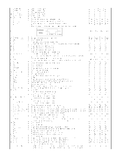
31 20MHz.IN I Main oscillator input --- STOP STOP ---
32 20MHz.OUT O Main oscillator output --- STOP STOP ---
33 +5V(D) I 5V input terminal --- --- --- ---
34 32KHz IN I Sub oscillator input --- --- --- ---
35 32KHz OUT O Sub oscillator output --- --- --- ---
36 NC(VCONT) I Video Control --- --- --- ---
37 V EE(L) O Output terminal for switch between EE and VV. Low Low Low Low
38 D REC(H) O Output terminal for video recording current control. Low Low Low Low
39 D.A.REC(H) O Control terminal for normal audio recording current. Low Low Low Low
Bias oscillation Control terminal for Linear audio recording current.
D.A.REC(H)
40 BIAS(L) O High Hi-Z Hi-Z High
BIAS(L)
140mS 140mS
41 FM.MUTE(H) O Output terminal for audio mute control. High High Low High
42 N.C -- (No Connection.) --- --- --- ---
Input terminal for the unit power button.
43 POWER_KEY I In In In In
It switches ON to OFF and/or OFF to ON when down edge is detected.
44 POS.SW3 I Input terminal for mecha position. In In In In
45 POS.SW2 I Input terminal for mecha position. In In In In
46 POS.SW1 I Input terminal for mecha position. In In In In
ON/OFF Control terminal for power circuit.
47 POWER OFF(H) O Power off condition: "High" is existed. High High Low High
("Low" is existed when the mechanism and/or circuit operation is activated.)
Output terminal for FIP on/off control signal.
48 FIP(L) O Not fix High Low Low
("Low" is existed when the power off condition under the "FIP OFF" setting.)
49 P50 IN I Input terminal for Project 50 serial signal. In In In In
50 N.C -- (No Connection.) --- --- --- ---
51 N.C -- (No Connection.) --- --- --- ---
52 RESET(L) I Input terminal for microprocessor reset. In In In In
53 4FC.LPF I 4fc clock input terminal --- --- --- ---
54 OSD.FSC IN I OSD clock input terminal --- --- --- ---
55 5V(OSD) I 5V input terminal --- --- --- ---
56 CVIN I Input terminal for Composite video signal. --- --- --- ---
57 GND(OSD) I GND --- --- --- ---
58 LECHA I Input terminal for Composite video signal.(White level) --- --- --- ---
59 20M.START(H) I Switching terminal for stertting Mode.(High speed/Low speed) --- --- --- ---
60 MD0 I Mode setting terminal for flash over-write. --- --- --- ---
61 CVOUT O Output terminal for CG Video. --- --- --- ---
62 HLF O LPF connecting terminal for the slicer. (For OSD dot clock.) --- --- --- ---
63 SECAM.V.IN I Chrominance input terminal for SECAM super impose. --- --- --- ---
64 GND I Connect to GND In In In In
Input terminal for the prevention tab.
65 S TAB(L) I In In In In
[EXIST] :LOW [NO EXIST] :HIGH
Control terminal for loading motor.
66 UNLOADING(H) O Low Low Low Low
[Reverse rotation / brake] : "High"
Control terminal for loading motor.
67 LOADING(H) O Low Low Low Low
[forward rotation / brake] : "High"
68 C.SYNC I Input terminal for composite V-sync signal. In In In In
69 EX.FF/REW(L) O Filter control terminal for PB-CTL signal in FF/REW. Low Low Low Low
70 PAL-I/BG/DK(SYS4) O Output terminal for TV broadcast system switching signal for video circuit control. Not fix Low Low Low
71 SECAM/PAL(SYS2) O Output terminal for TV broadcast system switching signal for video circuit control. Not fix Low Low Low
Output terminal for super power save mode setting.
72 SLEEP(L) O High Low Low High
P-OFF in the super power save mode "Low".
Switching terminal for NTSC FM Audio trap filter in PB.
73 PB60Hz(H) O [VV (PB,Trick_PB/A-DUB, A-DUB-PS) mode and CTL is 60Hz] : "High" Low Low Low Low
[Other than above condition] : "Low"
74 N.C -- (No Connection.) --- --- --- ---
75 N.C -- (No Connection.) --- --- --- ---
76 P FAIL(L) I Input terminal for Interrupt signal for power fail detection. In In In In
77 IR I Input terminal for Interrupt signal from IR sensor emitted by Remo-Con. In In In In
78 P50 OUT O Output terminal for Project 50 serial data. Not fix Low Low Low
79 CAP.ET O Output terminal for Capstan Torque command. 0V 0V Low 0V
80 CYL.ET O Output terminal for Cylinder Torque command. 4.213V 4.213V Low 4.213V
81 N.C -- (No Connection.) --- --- --- ---
82 HALF_WAVE(H) O Switching terminal for capstan driver speed mode.(FAST/SLOW) In In In In
83 CAP.R/F O Switching terminal for capstan motor rotating direction. Low Low Low Low
84 125Hz O 125Hz pulse output terminal for clock adjustment. Not fix Low Low Low
Short Circuit detection terminal for oscillation circuit in REC.
85 SHORT_DN I *When the "BIAS(H)" is "Low" and this terminal is "High", "F08" is displayed. In In In In
*When the "BIAS(H)" is "High" and this terminal is "low", "F07" is displayed.
◦ Jabse Service Manual Search 2026 ◦ Jabse Pravopis ◦ onTap.bg ◦ Other service manual resources online : Fixya ◦ eServiceinfo