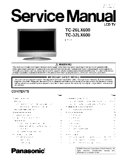
Service Manuals, User Guides, Schematic Diagrams or docs for : panasonic LCD LH58 TC-26LX600 TC-32LX600
<< Back | HomeMost service manuals and schematics are PDF files, so You will need Adobre Acrobat Reader to view : Acrobat Download Some of the files are DjVu format. Readers and resources available here : DjVu Resources
For the compressed files, most common are zip and rar. Please, extract files with Your favorite compression software ( WinZip, WinRAR ... ) before viewing. If a document has multiple parts, You should download all, before extracting.
Good luck. Repair on Your own risk. Make sure You know what You are doing.
Image preview - the first page of the document

>> Download LH58 TC-26LX600 TC-32LX600 documenatation <<
Text preview - extract from the document
                                                                                                                     MTNC060372CE
                                                                                                                    B05 Canada: B07


                                                                                                                     LCD TV
                                                                  TC-26LX600
                                                                  TC-32LX600
                                                                  LH58


CONTENTS
                                                           Page                                                              Page
1 Safety precautions                                          3    9 Disassembly Instructions                                        8
2 Warning                                                     3        9.1. Removing the LCD panel assembly and LCD L/R MTG 12
    2.1. Prevention of Electro Static Discharge (ESD) to               9.2. Removing the LCD panel and LCD T/B MTG               12
        Electrostatically Sensitive (ES) Devices              3   10 Measurements and Adjustments                                13
3 About lead free solder (PbF)                                4       10.1. White Balance Adjustment                             13
4 Receiver feature table                                      5   11 Boards Assemblies                                           14
5 Chassis Board Layout                                        6       11.1. AP-Board                                             14
6 Location of controls (EUR7613ZF0)                           7       11.2. A-Board                                              15
7 Service Mode                                                8       11.3. P-Board                                              16
    7.1. How to enter into adjustment mode                    8       11.4. G-Board                                              17
    7.2. Adjustment method.....Use the remote control.        8       11.5. DT-Board                                             18
    7.3. Cancellation                                         8       11.6. DT-Board with shield                                 19
    7.4. Contents of adjustment mode                          8       11.7. V-Board                                              20
8 Troubleshooting Guide                                       8   12 Block Diagram                                               21
    8.1. Self-check function                                  8       12.1. Block Diagramfor K, P and AP (DC-DC CONV.) (1of 2) 21
    8.2. How to access                                        8       12.2. Block Diagram for K, P and AP (DC-DC CONV.) (2of 2) 22
    8.3. Screen Display                                       8       12.3. ATSC Interface Block Diagram (1 of 2)                23
◦ Jabse Service Manual Search 2024 ◦ Jabse Pravopis ◦ onTap.bg ◦ Other service manual resources online : Fixya ◦ eServiceinfo