Service Manuals, User Guides, Schematic Diagrams or docs for : panasonic LCD PT-50LC13 PT-50LC13 SVC sc1_note
<< Back | HomeMost service manuals and schematics are PDF files, so You will need Adobre Acrobat Reader to view : Acrobat Download Some of the files are DjVu format. Readers and resources available here : DjVu Resources
For the compressed files, most common are zip and rar. Please, extract files with Your favorite compression software ( WinZip, WinRAR ... ) before viewing. If a document has multiple parts, You should download all, before extracting.
Good luck. Repair on Your own risk. Make sure You know what You are doing.
Image preview - the first page of the document
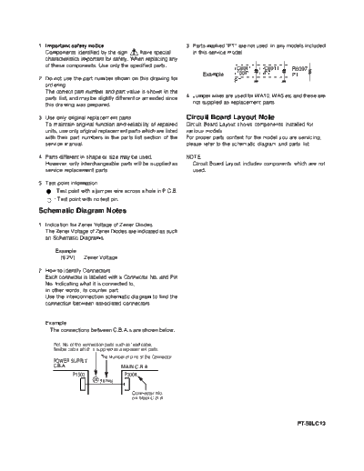
>> Download sc1_note documenatation <<
Text preview - extract from the document
1. Important safety notice                                            3. Parts marked "PT" are not used in any models included
   Components identified by the sign        have special                 in this service model.
   characteristics important for safety. When replacing any
   of these components. Use only the specified parts.
                                                                                           C6011      C6011       R6097
                                                                            Example:       100P       PT          PT
2. Do not use the part number shown on this drawing for                                   PT
   ordering.
   The correct part number and part value is shown in the
   parts list, and may be slightly different or amended since         4. Jumper wires are used for WA10, WA5 etc and these are
   this drawing was prepared.                                            not supplied as replacement parts.

3. Use only original replacement parts:                               Circuit Board Layout Note
   To maintain original function and reliability of repaired          Circuit Board Layout shows components installed for
   units, use only original replacement parts which are listed        various models.
   with their part numbers in the parts list section of the           For proper parts content for the model you are servicing,
   service manual.                                                    please refer to the schematic diagram and parts list.

4. Parts different in shape or size may be used.                      NOTE:
   However, only interchangeable parts will be supplied as              Circuit Board Layout includes components which are not
   service replacement parts.                                           used.

5. Test point information
      : Test point with a jumper wire across a hole in P.C.B.
       : Test point with no test pin.

Schematic Diagram Notes
1. Indication for Zener Voltage of Zener Diodes
   The Zener Voltage of Zener Diodes are indicated as such
   on Schematic Diagrams.

       Example:
         (6.2V)......Zener Voltage

2. How to identify Connectors
   Each connector is labeled with a Connector No. and Pin
   No. Indicating what it is connected to,
   in other words, its counter part.
   Use the interconnection schematic diagram to find the
   connection between associated connectors.


   Example:
    The connections between C.B.A.s are shown below.

      Ref. No. of the connection parts such as lead cable,
      flexible cable which is supplied as a replacement parts.
                               The Number of pins of the Connector.
      POWER SUPPLY
      C.B.A.                               MAIN C.B.A.
                P1503                       P3004
                           244 (10 Pins)

                                               Connector No.
                                               on Main C.B.A.


                                                                                                                    PT-50LC13
◦ Jabse Service Manual Search 2026 ◦ Jabse Pravopis ◦ onTap.bg ◦ Other service manual resources online : Fixya ◦ eServiceinfo