Service Manuals, User Guides, Schematic Diagrams or docs for : panasonic LED TX-42AX500E PCZ1402033CE doc 03_servicenavigation
<< Back | HomeMost service manuals and schematics are PDF files, so You will need Adobre Acrobat Reader to view : Acrobat Download Some of the files are DjVu format. Readers and resources available here : DjVu Resources
For the compressed files, most common are zip and rar. Please, extract files with Your favorite compression software ( WinZip, WinRAR ... ) before viewing. If a document has multiple parts, You should download all, before extracting.
Good luck. Repair on Your own risk. Make sure You know what You are doing.
Image preview - the first page of the document
>> Download 03_servicenavigation documenatation <<
Text preview - extract from the document
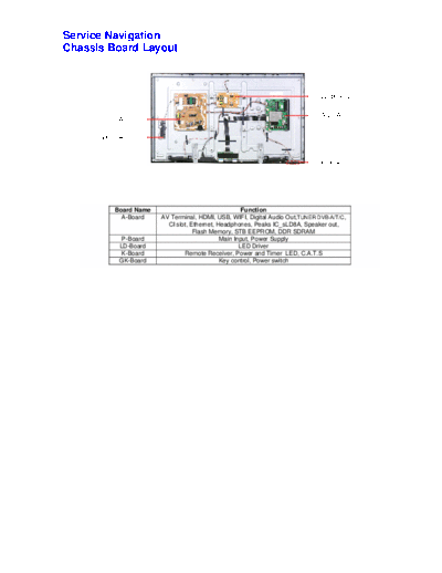
Service Navigation
Chassis Board Layout


                                                                             LD-BOARD


                                                                             A-BOARD
       P-BOARD

      GK-BOARD


                                                                             K-BOARD


         Board Name                                 Function
           A-Board    AV Terminal, HDMI, USB, WIFI, Digital Audio Out,TUNER DVB-A/T/C,
                        CI slot, Ethernet, Headphones, Peaks IC_sLD8A, Speaker out,
                                  Flash Memory, STB EEPROM, DDR SDRAM
           P-Board                          Main Input, Power Supply
          LD-Board                                 LED Driver
           K-Board            Remote Receiver, Power and Timer LED, C.A.T.S
          GK-Board                          Key control, Power switch
Service Hints
How to remove the backcover
Lay the main unit face down. (see Fig.5)


                                                                    Fig.5


Remove the 4 fixing screws and the pedestal assembly. (see Fig.6)


                                                                                                                                SCREWS
                                                                                                                        (1) THE5ZL002N /4pcs/


                                (1)                                                             (1)

                                                        (1)                   (1)


                                                                    Fig.6


Remove the 24 fixing screws and the backcover. (see Fig.7)

                                      (2)                            (2)                  (2)


         (2)                                                                                                      (2)          SCREWS
                                                                                                                        (2) THTD037J /17pcs/
                                                                                                                        (3) THEC1509 /7pcs/
                                                  (3)                               (3)
                                                                                                      (2)


                                                                                                (2)
         (2)                                                                                                (3)   (2)


                          (2)                     (3)                               (3)

                                                                                                  (2)


                                            (3)
         (2)                                                         (3)                                          (2)


                    (2)               (2)                                                 (2)               (2)
                                                              (1)           (1)

                                                                    Fig.7
Applicable Signals

 Component (Y, Pb, Pr) (from AV2 terminal), HDMI

           Signal name                      COMPONENT                                 HDMI

525 (480) / 60i,60p                                *                                   *
625 (576) / 50i, 50p                               *                                   *
750 (720) / 60p, 50p                               *                                   *
1,125 (1,080) / 60i, 50i                           *                                   *
1,125 (1,080) / 60p                                                                    *
1,125 (1,080) / 50p                                                                    *
1,125 (1,080) / 24p                                                                    *


Note:
             Signals other than above may not be displayed properly.
             The above signals are reformatted for optimal viewing on your display.
◦ Jabse Service Manual Search 2026 ◦ Jabse Pravopis ◦ onTap.bg ◦ Other service manual resources online : Fixya ◦ eServiceinfo