Service Manuals, User Guides, Schematic Diagrams or docs for : panasonic LED TX-42AX500E PCZ1402033CE doc 07_troubleshootingguide
<< Back | HomeMost service manuals and schematics are PDF files, so You will need Adobre Acrobat Reader to view : Acrobat Download Some of the files are DjVu format. Readers and resources available here : DjVu Resources
For the compressed files, most common are zip and rar. Please, extract files with Your favorite compression software ( WinZip, WinRAR ... ) before viewing. If a document has multiple parts, You should download all, before extracting.
Good luck. Repair on Your own risk. Make sure You know what You are doing.
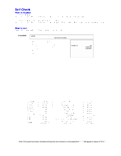
Image preview - the first page of the document
>> Download 07_troubleshootingguide documenatation <<
Text preview - extract from the document
Self Check
How to access
Self-check indication only:
While pressing [VOLUME ( - )] button on the main unit, press [OK] button on the remote control.

Self-check indication and forced to factory shipment setting:
While pressing [VOLUME ( - )] button on the main unit, press [MENU] button on the remote control for more than 3 seconds.


How to exit
Switch off the power with the [POWER] button on the main unit.


   TX-42AS500E
                     42FHD
                                                      Self Check Complete

                     H14TUN      O.K.      PEAKS-SOFT                3.008
                     H90STBY     O.K.      PEAKS-EEP           01.00.0206
                     H92MEM1     O.K.      LSI-PACKAGE               0.00c
                     H91MEM2     O.K.      LSI-RELEASE                0.08    MODEL ID                 0B
                     H17LAN      O.K.      STBY-SOFT               1.00.02                       030001B0
                     H71TC-DAC   O.K.      STBY-EEP             1.00.0021                        00000400
                     H96ID       O.K.
                     H97ID2      O.K.
                     H42WIFI     O.K.


                  Display           Ref. No.                        Description                     P.C.B.
               H14TUN               TU6705                      TUNER DVB-A/T/C/                   A-Board
               H90STBY              IC8000                     IC Peaks-sLD8A                      A-Board
               H92MEM1              IC8901                      EEPROM STM                         A-Board
               H91MEM2              IC8900                       Flash Memory                      A-Board
               H17LAN               IC8900                           MAC                           A-Board
                                    IC8000                      IC Peaks-sLD8A                     A-Board
               H71TC-DAC
                                 T-Con on Panel                 T-Con on Panel                  T-Con on Panel
               H96ID                IC8900                        CI+,DTCP-IP                      A-Board
               H97ID2               IC8900             Dimora, HDCP2, Netflix, Widevine,           A-Board
                                    IC8000                     IC Peaks-sLD8A                      A-Board
               H42WIFI
                                 N5HBZ0000109                     Wifi Dongle                     Wifi Dongle


     If the CCU ports have been checked and found to be incorrect or not located then " - - " will appear in place of "O.K.".
Power LED blinking timing chart
1.   Subject
     Information of LED Flashing timing chart.

2.   Contents
     When abnormality has occurred the unit, the protection circuit operates and reset to the stand by mode. At this time, the
     defective block can be identified by number of blinking of the Power LED on the front panel of the unit.


 Blinking
                                     Blinking timing                                 Contents                    Check point
  times
                       Once       4 sec
                                                       Light                                                      A BOARD
     1                                                                               BL_SOS
                                                       No Light
                                                                                                                 LD BOARD
                                                                                                                   PANEL

     3                                                                              IROM SOS                     A BOARD


     7                                                                               SUB3.3V                     A BOARD


     8                                                                                 SOS                       A BOARD
                                                                                                                  PANEL


     9                                                                            SOUND_SOS                      A BOARD


     12                                                                              BE_SOS                      A BOARD


     13                                                                           EMERGENCY                      A BOARD


LCD Panel Test Mode
Purpose:
To find the possible failure point where in LCD Panel or Printed Circuit Board when the abnormal picture is displayed.

How to Enter:
While pressing [VOLUME ( - )] button of the main unit, press [YELLOW] button of the remote control three times.

How to Exit:
Switch off the power with the [POWER] button on the main unit or the [POWER] button on the remote control.

How to confirm:
If the abnormal picture is displayed, go into LCD Panel test mode to display the several test patterns.
And then, judge by the following method.
Still abnormal picture is displayed: The cause must be in LCD Panel.
Normal picture is displayed: The cause must be in A board.

Remarks:
The test pattern is created by the circuit in LCD Panel.
In LCD Panel test mode, this test pattern is displayed unaffected by signal processing for RF or input signal.
If the normal picture is displayed, LCD Panel must be okay and the cause of failure must be in A board.
◦ Jabse Service Manual Search 2026 ◦ Jabse Pravopis ◦ onTap.bg ◦ Other service manual resources online : Fixya ◦ eServiceinfo