Service Manuals, User Guides, Schematic Diagrams or docs for : panasonic Micro wave oven NN-CD767 HAD0705001C2
<< Back | HomeMost service manuals and schematics are PDF files, so You will need Adobre Acrobat Reader to view : Acrobat Download Some of the files are DjVu format. Readers and resources available here : DjVu Resources
For the compressed files, most common are zip and rar. Please, extract files with Your favorite compression software ( WinZip, WinRAR ... ) before viewing. If a document has multiple parts, You should download all, before extracting.
Good luck. Repair on Your own risk. Make sure You know what You are doing.
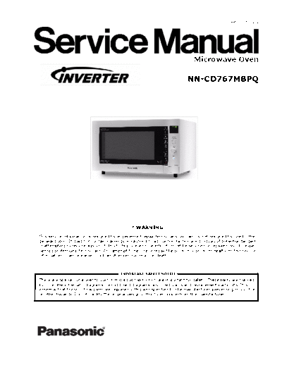
Image preview - the first page of the document

>> Download HAD0705001C2 documenatation <<
Text preview - extract from the document
                                                                                                    HAD0705001C2


                                                                                 Microwave Oven

                                                                              NN-CD767MBPQ
                                                                                          .
                                                                                          .
                                                                                          .


                                                 ! WARNING
This service information is designed for experienced repair technicians only and is not designed for use by the
general public. It does not contain warnings or cautions to advise non-technical individuals of potential dangers
in attempting to service a product. Products powered by electricity must be serviced or repaired only by expe-
rienced professional technicians. Any attempt to service or repair the product or products dealt with this service
information by anyone else could result in serious injury or death.


                                          IMPORTANT SAFETY NOTICE
There are special components used in this equipment which are important for safety. These parts are marked
by (!) in the schematic diagrams, circuit board diagrams, exploded views and replacement parts lists. It is
essential that these critical parts are replaced with parts specified by the manufacturer, preventing shock, fire
or other hazards. Do not modify the original design without permission from the manufacturer.
1 Contents
1   Contents .......................................................................................................... 2
2   Feature Chart ................................................................................................... 3
3   Control Panel ................................................................................................... 4
4   Inverter Warnings ............................................................................................ 5
5   Schematic Diagram ........................................................................................... 6
6   Wiring Diagram ................................................................................................ 7
7   Description of the Operating Sequence ............................................................... 8
8   Cautions to be Observed when Troubleshooting ...................................................10
9   Parts Replacement Procedure........................................................................... 12
10 Component Test Procedure............................................................................... 15
11 Measurements and Adjustments....................................................................... 17
12 Troubleshooting Guide..................................................................................... 18
13 Parts List........................................................................................................ 24
14 Exploded View................................................................................................. 26
15 Door Assembly................................................................................................ 27
16 Escutcheon Base............................................................................................. 28
17 Packing and Accessories.................................................................................. 29
18 Trim Kit Accessories........................................................................................ 30
19 Digital Programmer Circuit............................................................................... 31


          BPQ
            Power source                 240V AC Single Phase 50Hz
            Power requirements           Microwave 1170W
                                         Grill 1360W
                                         Convection 1470W
                                         Convection + Grill 2770W
                                         Micro + Grill Combi 2400W
                                         Micro + Convection Combi 2515W
                                         Micro + Grill + Convection Combi 2515W
            Output (IEC60705)            Microwave 1000W
                                         Grill 1300W
                                         Convection 1400W
            Microwave frequency          2450Mhz
            Timer                        99 min 99 second
            Oven cavity size             27L
            Outside dimensions           510mm(W) x 477mm(D) X 304MM (H)


                                                           2
2 Feature Chart


Function          BPQ
Microwave         6
Grill             3
Convection        17
Combi             Yes
Sensor Reheat     -
Sensor Cook       -
Sensor Combi      -
Weight Defrost    3
Weight Combi      8
Weight Reheat     4
Weight Cook       2
Memory Cook       3
Weight Crisp      -
Stage Cooking     3 stage
Delay / Stand     Yes
More / Less       No
Kg -> lb/oz       Yes
Clock             12h
Word Prompt       English
Step by Step      No


                            3
3 Control Panel


                  4
4 Inverter Warnings
The inverter circuit board supplies the magnetron tube with a very high voltage (4000 volts).


                        Danger
◦ Jabse Service Manual Search 2024 ◦ Jabse Pravopis ◦ onTap.bg ◦ Other service manual resources online : Fixya ◦ eServiceinfo