Service Manuals, User Guides, Schematic Diagrams or docs for : panasonic PDP National Training GP9DE THxxPX60, THxxPX600 SERVICE GUIDE

<< Back | Home

Most service manuals and schematics are PDF files, so You will need Adobre Acrobat Reader to view : Acrobat Download Some of the files are DjVu format. Readers and resources available here : DjVu Resources
For the compressed files, most common are zip and rar. Please, extract files with Your favorite compression software ( WinZip, WinRAR ... ) before viewing. If a document has multiple parts, You should download all, before extracting.
Good luck. Repair on Your own risk. Make sure You know what You are doing.


Image preview - the first page of the document
GP9DE THxxPX60, THxxPX600 SERVICE GUIDE


>> Download GP9DE THxxPX60, THxxPX600 SERVICE GUIDE documenatation <<

Text preview - extract from the document
Panasonic


   THxxPX60, THxxPX600, GP9DE CHASSIS
             SERVICE GUIDE
OVERVIEW OF BOOT UP SEQUENCE FOR PSU:

    5-1. Power Supply Overview (1/2)
     
                                                                                                                 Power SW

    AC Plug
              P                                                     SS
                                                    12V
                                       Standby
                                        Power
                                                                                                        STB_PS          S
                                        Circuit
                                                                    D                          DG
                                              STB_5V
                                                                 Panel_ON                Panel_STB_ON
                            Relay                                             Micom
                                                                              Micom
                            ON/OFF      Power
                  Relay                 Power                                                             Micom
                                         MCU                                                              Micom
                                         MCU                                               TV_SUB_ON


                                     Vlow         F_STB
                                     ON/OFF       ON/OFF
                                                                                               TV_MAIN_ON
                                              Vsus                  PA
                                               ON/OFF                                 MAIN/SUB 5V
                                                                F_STB_14V
                                                                                      MAIN SUB 9V
                                                     CONV.                    CONV.


                                                                            15V
                   PFC                  ACFB         SW                     Vsus
                  Circuit               Circuit
                                                           SW               Vda


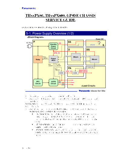
   1. The voltage driving each circuit is made by P board.
   2. The circuit of P board consists of "standby power circuit", "PFC circuit" and
      "ACFB circuit".
   STANDBY produces 5V and 12V, PFC produces 390V, ACFB produces Vsus,
   Vda, 15V, 12V
   3. These power circuits are controlled by micros on P board and D, DG boards.
   4. DG BOARD PSU CONTROL SIGNALS:


◦ Jabse Service Manual Search 2024 ◦ Jabse PravopisonTap.bg ◦ Other service manual resources online : FixyaeServiceinfo