Service Manuals, User Guides, Schematic Diagrams or docs for : panasonic TV 17LC4 sksm0820
<< Back | HomeMost service manuals and schematics are PDF files, so You will need Adobre Acrobat Reader to view : Acrobat Download Some of the files are DjVu format. Readers and resources available here : DjVu Resources
For the compressed files, most common are zip and rar. Please, extract files with Your favorite compression software ( WinZip, WinRAR ... ) before viewing. If a document has multiple parts, You should download all, before extracting.
Good luck. Repair on Your own risk. Make sure You know what You are doing.
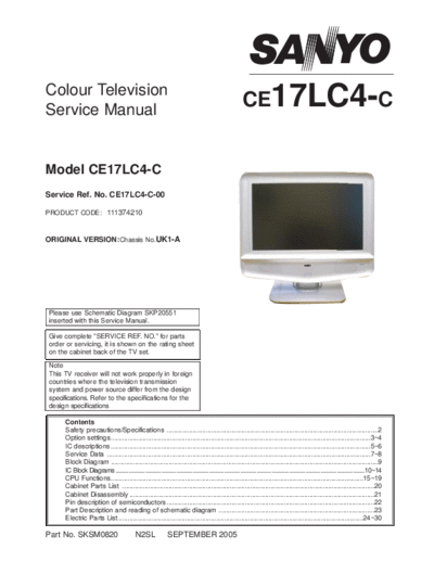
Image preview - the first page of the document
>> Download sksm0820 documenatation <<
Text preview - extract from the document
Colour Television
Service Manual
CE17LC4-C
Model CE17LC4-C
Service Ref. No. CE17LC4-C-00
PRODUCT CODE: 111374210
ORIGINAL VERSION: Chassis No.UK1-A
Please use Schematic Diagram SKP20551
inserted with this Service Manual.
Give complete "SERVICE REF. NO." for parts
order or servicing, it is shown on the rating sheet
on the cabinet back of the TV set.
Note
This TV receiver will not work properly in foreign
countries where the television transmission
system and power source differ from the design
specifications. Refer to the specifications for the
design specifications
Contents
Safety precautions/Specifications ..................................................................................................................2
Option settings ............................................................................................................................................3~4
IC descriptions ............................................................................................................................................5~6
Service Data ..............................................................................................................................................7~8
Block Diagram ................................................................................................................................................9
IC Block Diagrams........................................................................................................................................................................10~14
CPU Functions........................................................................................................................................15~19
Cabinet Parts List ........................................................................................................................................20
Cabinet Disassembly ....................................................................................................................................21
Pin description of semiconductors ................................................................................................................22
Part Description and reading of schematic diagram ....................................................................................23
Electric Parts List ....................................................................................................................................24~30
Part No. SKSM0820 N2SL SEPTEMBER 2005
SAFETY PRECAUTION
1: An isolation transformer should be connected in the 3: When replacing a chassis in the cabinet, always be
power line between the receiver and the AC line certain that all the protective devices are installed
when a service is performed on the primary of the properly, such as, control knobs, adjustment covers
converter transformer of the set. or shields, barriers, isolation resistor-capacitor networks
etc. Before returning any television to the customer,
2: Comply with all caution and safety-related notes the service technician must be sure that it is completely
provided on the cabinet back, inside the cabinet, on safe to operate without danger of electrical shock.
the chassis or the picture tube.
X-RADIATION PRECAUTION
The primary source of X-RADIATION in the television receiver is the picture tube. The picture tube is specially
constructed to limit X-RADIATION emissions. For continued X-RADIATION protection, the replacement tube
must be the same type as the original including suffix letter. Excessive high voltage may produce potentially
hazardous X-RADIATION. To avoid such hazards, the high voltage must be maintained within specified limit.
Refer to this service manual, high voltage adjustment for specific high voltage limit. If high voltage exceeds
specified limits, take necessary corrective action. Carefully follow the instructions for +B1 volt power supply
adjustment, and high voltage adjustment to maintain the high voltage within the specified limits.
PRODUCT SAFETY NOTICE
Product safety should be considered when a component replacement is made in any area of a receiver.
Components indicated by mark ! in the parts list and the schematic diagram designate components in which
safety can be of special significance. It is particularly recommended that only parts designated on the parts list in
this manual be used for component replacement designated by mark ! . No deviations from resistance wattage
or voltage ratings may be made for replacement items designated by mark ! .
SPECIFICATIONS
Power source AC 220~240V, 50Hz
Television system System I
Colour system PAL/NTSC4.43 (PAL/NTSC4.43/NTSC3.58 IN AV MODE)
Receiving channel UHF: #21~69
Aerial input impedance 75ohm
Rear AV terminal
AV1: CENELEC standard
INPUT: Composite video, RGB and Audio L/R
OUTPUT: TV-output with composite video and audio L/R
AV2: CENELEC standard
INPUT: Composite video, RGB, S-VHS and Audio L/R
OUTPUT: Monitor output with composite video and Audio L/R
Front AV terminal
AV3: RCA jacks
INPUT: Composite video and Audio L/R
Sound output(Music) 12 x 2
Dimensions (WxHxD) 452 x 409 x 237mm
Weight 6.5 Kg
Important recycling information.
Your SANYO product is designed and manufactured with high quality
materials and components which can be recycled and reused.
This symbol means that electrical and electronic equipment, at their
end-of-life, should be disposed of separately from your household
waste.
Please dispose of this equipment at your local community waste collec-
tion / recycling centre.
In the European Union there are separate collection systems for used electrical and electronic
products.
Please help us to conserve the environment we live in!
Note: This symbol mark and recycle system are applied only to EU countries and are not applied
to other countries of the world.
-2-
N2SL
OPTION SETTING
To enter to the Option Mode
+ Press and hold the F/OK button on the remote control and Pw button on the front panel of the TV. The option win-
dow will appear on the screen.
Option
OSD H-Pos 6
Country EU
Sort Mode SORTING
Plug & Play ON
Welcome Text ON
Surround ON
Bass Feature BBE+Bass Exp
AVL OFF
AV3 ON
Colour System OFF
AFC OFF
Program Name ON
Text no signal ON
Blue Back OFF
Digital Mode OFF
Scart 2
OPTION MODE FOR CE17LC4-C-00
To set the Option Mode
+ Highlight the desired option item by using the Pv or Pw button .
+ To switch the option mode, use the Volume - (LEFT) or Volume + (RIGHT) button.
+ The data which is set in the option mode is stored into the memory IC automatically.
The following table shows the available option items and default setting mode.
Option Mode Mode Description & Note
OSD H-POS Set value to 6
COUNTRY EU or UK Country default "EU"
SORT MODE Sort mode, default "Sorting"
PLUG & PLAY ON or OFF Plug & Play mode, default "ON"
WELCOME TEXT ON or OFF Welcome Text default "ON"
SURROUND ON or OFF Surround sound default "ON"
BASS FEATURE Bass Feature default "BBE+Bass Exp"
AVL ON or OFF AVL mode, default "OFF"
AV3 ON or OFF AV3 mode, default "ON"
COLOUR SYSTEM ON or OFF Colour system, default "OFF"
AFC ON or OFF AFC mode, default "ON"
PROGRAM NAME ON or OFF Program name default "OFF"
TEXT NO SIGNAL ON or OFF Disables Text when no signal, default "ON"
BLUE BACK ON or OFF Blue Black mode, default "OFF"
DIGITAL MODE ON or OFF Digital mode, default "OFF"
SCART Set value to 2
Exit from the Option Mode
+ Press the MENU i button.
-3-
N2SL
N2SL
Analogue Settings for All UK1A N2R* and N2S*
N2RJ N2RK N2RL N2SJ N2SL
PICTURE
Brightness 38 38 38 25 25
Contrast 50 50 50 50 50
Colour 30 30 30 33 33
Sharpness 35 35 35 35 35
Brightness 47 47 47 30 30
OPTION SETTINGS
Contrast 63 63 63 63 63
Colour 35 35 35 40 40
Sharpness 40 40 40 40 40
Brightness 31 31 31 25 25
Contrast 32 32 32 35 35
Colour 30 30 30 35 35
Sharpness 32 32 32 35 35
Dyn skin tone Off Off Off Off Off
TXT Brightness Max Max Max Max Max
SOUND
Volume 10 10 10 10 10
Balance 0 0 0 0 0
Bass 0 0 0 0 0
Treble 0 0 0 0 0
-4-
Sound Preset Normal Normal Normal Normal Normal
BBE Off Off Off Off Off
Surround Off Off Off Off Off
OPTION
OSD H-Pos 6 6 6 6 6
Country EU UK EU EU EU
Sort Mode Sorting Sorting Sorting Sorting Sorting
Plug+Play On On On On On
Welcome Txt On On On On On
Surround On On On On On
Bass Feature BBE+Bass Exp BBE+Bass Exp BBE+Bass Exp BBE+Bass Exp BBE+Bass Exp
AVL Off Off Off Off Off
AV3 On On On On On
Colour System Off Off Off Off Off
AFC Off Off Off Off Off
Program Name On On On On On
TXT no signal On On On On On
Blue Back Off Off Off Off Off
Digital Mode Off On Off Off Off
Scart 2 2 2 2 2
IC Descriptions for UK1A
IC001
This is an LA42052 which is the audio amplifier for the set. It has left and right inputs from the LOC and left and right
outputs to the speakers and headphone socket. It also has mute and standby functions which are activated by the
LOC as appropriate.
IC1101 (monitor sets only)
This is a switching IC, NJM2233BM, which allows the sync signal input on monitor sets to be switched between pin
20 of SCART 1 (conventional & ALBOS) and pin 14 of SCART 1 (SIS signal). The IC takes a 5V supply and is
switched by the control line SC2_8, which is normally used for SCART 2 pin 8 signalling but is adapted fro the moni-
tor sets.
IC1205
This a ROHM BA7603F triple video switch which allows the RGB input to be switched between SCART 1 and
SCART 2. The switch is controlled by the RGB_SW line from the IC.
IC2001
This is a picture improvement chip, Philips TDA9178, which takes a YUV input from the LOC and carries out vector
processing of luminance and colour to improve overall picture quality and reduce noise. The IC requires an 8V
power supply and is also connected to the I2C bus.
IC201
This is the Philips LOC 1 chip which is the main system processor. It consists of three ICs encapsulated in one BGA
package with 388 balls. The "Cosmic" and "Picasso" chips carry out analogue and digital processing respectively,
and together from the UOC III which is used in many other sets. These are complemented by the Lithium IC which
carries out digital processing and scaling functions.
The IC requires 5V, 3.3V and 1.8V for correct operation ◦ Jabse Service Manual Search 2026 ◦ Jabse Pravopis ◦ onTap.bg ◦ Other service manual resources online : Fixya ◦ eServiceinfo