Service Manuals, User Guides, Schematic Diagrams or docs for : panasonic Video NV-HV61GN NV-HV61GN_NV-HV61EE_NV-HV61GCU_NV-HV61GH_NV-HV61GHT_NV-HV61PX SVC ds0501io

<< Back | Home

Most service manuals and schematics are PDF files, so You will need Adobre Acrobat Reader to view : Acrobat Download Some of the files are DjVu format. Readers and resources available here : DjVu Resources
For the compressed files, most common are zip and rar. Please, extract files with Your favorite compression software ( WinZip, WinRAR ... ) before viewing. If a document has multiple parts, You should download all, before extracting.
Good luck. Repair on Your own risk. Make sure You know what You are doing.


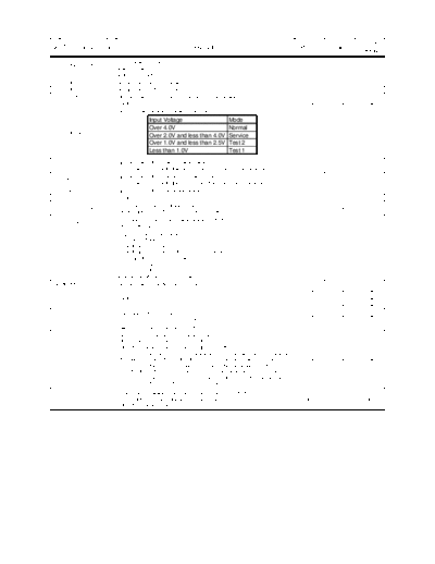
Image preview - the first page of the document
ds0501io


>> Download ds0501io documenatation <<

Text preview - extract from the document
                                                                                                                                   Reset/
No Terminal Name I/O                                            Description                                   P.OFF   P.Failure
                                                                                                                                  Release
                         Port for scanning line control:
    PROGRESSIVE TV
1                    I   scanning line 628: H                                                                  Low      Low         Low
    (L)
                         scanning line 624: L
2 CODE1              I   AD input terminal for model setting.                                                   In       In          In
3 CODE2              I   AD input terminal for model setting.                                                   In       In          In
4 T.S.CUREVE         I   Input terminal for "S-Curve" of Tuner AFC at channel selecting.                        In       In          In
5 NC                 O Low fix.                                                                                Low      Low         Low
                       Factory mode/ Service mode setting terminal.
                                         Input Voltage                            Mode
                                         Over 4.0V                                Normal
6 NORM/SERV/T2/TEST I                                                                                           In       In          In
                                         Over 2.0V and less than 4.0V             Service
                                         Over 1.0V and less than 2.5V             Test 2
                                         Less than 1.0V                           Test 1

                         Input terminal of the Tape End sensor detection.
7 S-PHOTO            I                                                                                          In       In          In
                          *More than 2.6V : Black tape part.   *Less than 2.4V :Trans. Tape part.
                         Input terminal of the Tape Beginning sensor detection.
8 T-PHOTO            I                                                                                          In       In          In
                          *More than 2.6V : Black tape part. *Less than 2.4V :Trans. Tape part.
9 TRACKING_ENVE      I   Input terminal of the Video envelope signal.                                           In       In          In
10 NC                O Low fix.                                                                                Low      Low         Low
                         Control terminal for the Capstan current limit.                                        In                   In
11 CURRENT.LIMIT     O                                                                                                  Low
                         (Output impedance: MIN:1K, TYP:2.5K, MAX:4.0K)                                       DA=0V                DA=0V
                         Chip Select terminal for NAVI Data backup EEPROM.
12 EEPROM_CS         O                                                                                         High     Low         Low
                         *Active Low output.
                       Output terminal for the Artificial V-sync.
                       1. In trick playback.
                           Artificial V sync inserting timing : High
                           Artificial H sync inserting timing : Hi-Z (M output)
13 ART.V/H/N         O                                                                                         Low      Low         Low
                           Except above conditions : Low
                       2. NAVI REC : Hi-Z
                       3. OSD REC : Hi-Z
                       4. Other than above conditions : Low
14 REMOCON           I   Input terminal for the Remote Controller.                                              In       In          In
15 PICT1             O Control terminal for the Picture mode.                                                  Low      Low         Low
16 NC                O Low fix.                                                                                Low      Low         Low
17 PICT2             O Control terminal for the Picture mode.                                                  Low      Low         Low
                       Video head switching signal
18 VIDEO.H.SW        O                                                                                         Low      Low         Low
                          *L'/R="High"           *R'/L="Low"
19 AUDIO.H.SW        O Head switching signal for Audio circuit.                                                Low      Low         Low
                       Recording control signal for Hi-Fi Audio signal.
                       *REC, INSERT, AV INSERT:"High" is output. (Rec on)
                       *Other than above condition: "Low" is output. (Rec off)
                       *From L to H: Switching timing of this signal is synchronized with the HSW edge just
20 D.FM.REC          O after switching timing of "D33 of IC3001 = 0 to 1". (The delay is within 1 edge)        Low      Low         Low
                       *From H to L: When Editing, this switching timing is before the switching timing of
                       "D33 of IC3001 = from 1 to 0" by 60 +- 10msec in SP mode, by 100 +- 10msec in
                       LP/EP mode. When normal rec mode, this switching timing is before the switching
                       timing of "D33 of IC3001 = from 1 to 0" by 0 ~ 150msec.
                       Write protection releasing terminal for RAM correction EEPROM.
21 R_COLE_W (L)      O *During ROM correction data being Written: "Low" is output.                             Hi-Z     Hi-Z        Hi-Z
                       *Other than above condition: Hi-Z.
                                                                                                                                      Reset/
No Terminal Name I/O                                       Description                                           P.OFF   P.Failure
                                                                                                                                     Release
22 NC             O Low fix.                                                                                      Low      Low         Low

                       Enforced Normal selection signal and Audio Automatic Adjustment Trigger Input
                       Terminal
23 ABS_NORMAL     I     *To turn audio into normal: Low                                                            In       In         In
                        (During ADUBPS, HiFi Audio envelope deterioration)
                        *Others: High

                    Recording on/off control signal terminal for Linear audio.
                    1.When recording linear audio, take IC3001 D33, BIAS (H) and timing as below.
24 D.A.REC(H)     O *During Initial recording, at about same timing for D33=0       1, Bias=High.                 Low      Low         Low
                     *When finished recording, BIAS (H)=H          L, after 140+-10msec, set to Low.
                    2.Other than above, Output=Low

25 PAL 9H (H)     O PAL 9H: High is output.                                                                       Low      Low         Low

                    Linear Audio recording/ erasing On/ Off control terminal.
                    1.When recording Linear Audio, at about same timing of D33, Output=Low.
                      Output mode: REC, A. DUB, AV_INSERT
                     *When initiating recording D. A. REC (H)=L       H, after 140+-10msec set to High.
26 BIAS(H)        O                                                                                               Low      Low         Low
                     *When completing recording (Without delay) Output=Low
                    2.Wnen erasing TAPE REFRESH, Output=HIgh
                    3.Other than above, Output=Low
                    4.When models without DUB, can control ERASE ON/OFF.

                       SAFETY TAB DETECTION
27 STAB(L)        I     *With SAFETY TAB: "Low"                                                                    In       In         In
                        *Without SAFETY TAB:"High"

                       Audio mute control terminal.
                        High output (AUDIO MUTE).
28 FM_MUTE        O                                                                                               Hi-Z      In         In
                        The voltage is shifted to Hi-Z for reucing the current at 3 second after the power has
                        been turned on .

                       AUDIO SYSTEM (TUNER PRESET)=BG, I: High output
29 SW1            O                                                                                               Low      Low         Low
                       AUDIO SYSTEM (TUNER PRESET)=DK, M: Low output
                       Input terminal for mechanism position.
                                 SW4 SW3 SW2 SW1 Position Name
30 POS.SW4        I                                                                                                In       In         In
                                  1   1   1   0 EJECT Position
                                  0   0   1   0 DOWN Position
                                  0   0   1   1 R-REW Position
                                  0   1   0   0 LOAD Position
31 POS.SW3        I                                                                                                In       In         In
                                  0   1   0   1 REV Position
                                  0   1   1   0 PLAY Position
                                  0   1   1   1 P_OFF Position
                                  1   0   0   0 STOP_R Position
32 POS.SW2        I                                                                                                In       In         In
                                  1   0   0   1 STOP_F Position
                                  1   1   0   0 FF/REW Position
                                  1   1   1   0 FF2 Position
                                                 Intermediate Positions
33 POS.SW1        I               1   1   1   1 between each                                                       In       In         In

                                                 Positions
34 RESET          I    RESET Terminal.                                                                             In       In         In
35 32KHz.IN       I    Sub clock (32.768KHz) osc. input terminal.                                                  In       In         In
36 32KHz.OUT      O Sub clock (32.768KHz) osc. output terminal                                                    Out       Out        Out
37 5V(D)          -    VCC (5V) for Digital port                                                                   -         -          -
38 12MHz.IN       I    Main clock (12MHz) osc. input terminal.                                                     In       In         In
39 12MHz.OUT      O Main clock (12MHz) osc. output terminal.                                                      Out       Out        Out
40 GND(OSC)       -    Digital GND for OSC circuit.                                                                -         -          -
                    3.58NTSC (D6=0, D7=0 both of IC3001): High output
41 PAL PB (L)     O                                                                                               Low      Low         Low
                    Other than above                   : Low output
                                                                                                                                                 Reset/
No Terminal Name I/O                                             Description                                          P.OFF        P.Failure
                                                                                                                                                Release
                           50Hz Playback on SQPB: High output
42 PAL_SQPB           O                                                                                                 Low          Low          Low
                           Other than above    : Low output
                           Clock souce selection terminal at reset starting.
43 32K.START(L)        I    *12/16MHz(High speed) :Connected to VCC (5V).                                                 In           In           In
                            *32KHz(Slow speed) :Connected to Vss (0V).
44 LC.OSC.IN           I   Input terminal of the LC Oscillation (For OSD dot clock)                                       In           In           In
45 LC.OSC.OUT         O Output terminal of the LC Oscillation (For OSD dot clock)                                        Out          Out          Out
46 GND                 -   Connected to the GND ( Test terminal "B" in the factory).                                      -            -            -
47 FSC.LPF             I   OSC Filter connection terminal for Internal sync generator.                                    In         Low            In
48 FSC.IN              I   Sub carrier (fsc) input terminal for sync generator.                                           In         Low            In
49 GND(OSD)            -   GND terminal for OSD circuit.                                                                  -            -            -
50 CVIN                I   Input terminal for composite video signal.                                                     In           In           In
                           When a signal that V-sync is 50Hz is putting in or playing back.
                           * PAL/MESECAM distinction result input terminal.
                              Low is put into this terminal: PAL
                              High is put into this terminal: Dipend on MESECAM H /SECAM DET input
                           terminal.
51 KILLER              I                                                                                                  In           In           In
                           When a NTSC signal is putting in.
                           * Input terminal for distinction result of agreement between Fsc of input signal and
                           frequency of OSC for sub-carrier that being chosen by IC3001.
                              Low is put in: Agree
                              High is put in: Different
52 CVOUT              O Output terminal for the composite video signal.                                                  Out          Out          Out
53 5V(OSD)             -   Power supply terminal for OSD                                                                  -            -            -
54 HLF                 I   LPF connection terminal for slicer.                                                            In           In           In
55 VHOLD               I   Capacitor connection terminal of the Reference voltage generator circuit for the slicer.       In           In           In
56 CVIN(EDS)           I   Composite video signal input terminal for the slicer.                                          In           In           In
57 GND                 -   Connect to the GND (Test terminal "A" in the factory).                                         -            -            -
58 NC                 O Low fix.                                                                                        Low          Low          Low
     SECAM MIX (For
     other than NV-    I   SECAM CHROMA signal input terminal for SECAM SIGNAL SUPER IMPOSE.                            Low          Low          Low
     HV61GN)
59
     NC (For NV-
                      O Low fix.                                                                                        Low          Low          Low
     HV61GN)

                        OSD REC control terminal.
                        1. During OSD REC.
60 CHARA + HEM        O *During OSD character is output (Including Hemming): "High" is output.                        Hi-Z/Low     Hi-Z/Low     Hi-Z/Low
                        *Output than above condition: "Low" is output.
                        2. Other than OSD REC: High-Z.

                        (For NV-HV61GN)
                        High fix.
61 SW2                O (For other than NV-HV61GN)                                                                      Low          Low          Low
                          AUDIO SYSTEM = BG, DK: High is output.
                          AUDIO SYSTEM = I, M: Low is output.

                          AGC gain selection signal for tuner CH selection.
62 A.SEARCH (L)       I/O During digital AFC is working at TUNER PRESET mode: Low (AGC is high speed).                  Low          Low          Low
                          Other than above: Hi-Z (AGC is normal speed).

                        NAVI writing terminal.
                         * During NAVI data being written (During recording when JET NAVIGATOR is ON).
63 VBI2               O     OSD letters (Including the masking) being written : High                                  Low / Hi-Z   Low / Hi-Z   Low / Hi-Z
                            Except OSD letters being written : Low
                         * Other than above: Hi-z
                                                                                                                                               Reset/
No Terminal Name I/O                                           Description                                         P.OFF         P.Failure
                                                                                                                                              Release
                      Terminal for both NAVI Writing and OSD REC Writing.
                      1. During NAVI writing (During recording in JET NAVIGATOR is ON)
                          At NAVI data "H" being written : High is output
                          At NAVI data "L" being written : Low is output
64 VBI1/CHARA       O     At except NAVI data being written : Low is output                                       Low / Hi-Z     Low / Hi-Z   Low / Hi-Z
                      2. During OSD REC (During recording in OSD REC is ON)
                          During OSD letters (Except the masking) being written : High is output
                          Except OSD letters being written : Low
                       * Other than above condition : Hi-z
65 UNLOADING(H)     O Control terminal for the Unloading operation.                                                  Low           Low           Low
                      Chip select signal for FIP driver.
66 FLD_CS           O                                                                                            (Normal ope.)     Low           Low
                        *Active: "Low"           *Non-active: "High"
67 LOADING(H)       O Control terminal for the loading operation.                                                    Low           Low           Low
68 IC.DATA.OUT      O Timer-Bus signal for peripheral ICs control: Data output                                   (Normal ope.)       In         Hi-Z
69 IC.DATA.IN        I   Timer-Bus signal for peripheral ICs control: Data input                                 (Normal ope.)       In           In
70 IC.DATA.CLK      O Timer-Bus signal for peripheral ICs control:Clock outout                                   (Normal ope.)       In         Hi-Z
71 IIC.CLK          O Serial communication terminal (IIC) for IC3001/FM audio IC.                                (Normal ope.)       In         Hi-Z
72 IIC.DATA         I/O Serial communication terminal (IIC) for IC3001/FM audio IC.                              (Normal ope.)       In         Hi-Z

                      ROM Correction confirmation mode:
                       * ROM correction setting bit is "ON": "High".
73 125Hz/ROM.CORE   O  * ROM correction setting bit is "OFF": "Low" is existed.                                  (Normal ope.)     Low           Low
                         (Other than ROM Correction confirmation mode, this terminal is the output
                         terminal of internal clock for main clock adjustment.:Outputting the 125Hz.)

                         The rotation direction control terminal of the capstan driver.
74 CAP R/F          O                                                                                                Low           Low           Low
                           *RVS="High"         *FWD="Low".
75 NC               O Low fix.                                                                                       Low           Low           Low
                      Power supply terminal for the capstan motor control.
                                                                                                                   High                         High
76 CAP.ET           O (Conpared with the driver reference voltage, when it is "low", current will be cut. Also                     Low
                                                                                                                  PWM=0V                       PWM=0V
                      when it is "high", the rotation speed will be accelerated.)

                      Power supply terminal of the cylinder motor control:                                         Low                          Low
77 CYL.ET           O (Conpared with the driver reference voltage, when it is "high", current will be cut.       PWM=2.800         Low        PWM=2.800
                      Also when it is "low", the rotation speed will be accelerated. (Max:2.8V))                    V                            V
                         Input terminal for the power failar detection.
78 P.FAIL(L)         I                                                                                                In             In           In
                         Power failar : "Low".
79 S.REEL.PULSE      I   Input terminal of the S.Reel pulse.                                                          In             In           In
80 T.REEL.PULSE      I   Input terminal of the T.Reel pulse.                                                          In             In           In
                      REC MODE DATA
81 SP(L)            O  *N2H/P3H:"Low"                                                                                Low           Low           Low
                       *N4H/N6H/N10H/P6H/P9H:"High"

                        Control signal filter select terminal in FF/REW mode.
82 EX.FF/REW (L)    I/O *During FF/REW: Hi-Z                                                                         Low           Low           Low
                        *Except FF/REW: Low
                         ON/OFF control terminal for the VCR Power.
83 P.ON(H)          O                                                                                                Low           Low           Low
                         *Power ON : "High" *Power OFF : "Low"
84 AVR (L)          I/O Simplified AI playback ON/OFF control.                                                       Low           Low           Low
                         The distinction results whether S-VHS or VHS of the playback tape is input in VV
                         mode.
                         *"Low" is input: VHS tape playback.
                         *"High" is input: S-VHS tape playback.
                         NOTE: When the MESECAM (H) terminal receives "High", above result is invalidated
85 SQPB (H)          I                                                                                                In             In           In
                         and the tape is judged to VHS tape playback.
                         *In case of model having SQPB function, ON/OFF setting of SQPB is performed with
                         above result, Envelope voltage and result wheather the CTL pulse exists not.
                         *In case of model not having SQPB function, above result is disregarded, and the
                         VCR is always set to SQPB = off.
86 FG.AMP.OUT       O Output terminal for the Capstan FG AMP signal.                                                 Out            Out          Out
87 FG.AMP.IN         I   Input terminal for the Capstan FG AMP signal.                                                In             In           In
88 GND(A)            -   GND for Analogue circuit.                                                                     -             -            -
                                                                                                                             Reset/
No Terminal Name I/O                                         Description                               P.OFF    P.Failure
                                                                                                                            Release
                       Distinction terminal for the Video system.
                       1. In the VV mode.
                       *"High" is input: Playback of a MESECAM recorded tape.
                       *"Low" is input: Playback of other than MESECAM recorder tape.
                       2. In the EE mode.
89 MESECAM (H)    I    *"High" is input: Receiving a SECAM broadcast, or a SECAM signal is input.        In         In         In
                       NOTE:
                       *In case of model having MESECAM / SECAM REC/PLAY, the video system is
                       controlled with above result.
                       *In case of model do not having MESECAM / SECAM REC/PLAY, the above result is
                       invalidated.
90 CYL.PFG        I    Input terminal for the Cylinder PG/FG.                                            In         In         In
91 OREF           O 1/2 VDD reference voltage output terminal for the Analogue AMP.                     Out        Out        Out
92 IREF           I    1/2 VDD reference voltage input terminal for the Analogue AMP.                    In         In         In
93 GND            I    GND                                                                               In         In         In
94 CTL.HEAD(-)   I/O I/O terminal for the Control head (-)                                             In/Out     In/Out     In/Out
95 CTL.HEAD(+)   I/O I/O terminal for the Control head (+)                                             In/Out     In/Out     In/Out
96 CTL.AMP.REF    I    Capacitor connection terminal for reference of the control AMP.                   In         In         In
97 PB.CTL.OUT     O Output terminal for the Control AMP.                                                Out        Out        Out
98 5V(A)          -    Power supply terminal for Analogue AMP.                                           -          -          -
99 5V(AD)         -    Reference power supply terminal for the AD/8bit DA                                -          -          -
                    Output terminal for playback mode.
100 NTSC (L)      O                                                                                     Low       Low         Low
                    *50Hz: "High" *60Hz: "Low"


◦ Jabse Service Manual Search 2026 ◦ Jabse PravopisonTap.bg ◦ Other service manual resources online : FixyaeServiceinfo