Service Manuals, User Guides, Schematic Diagrams or docs for : panasonic Video R4 Mechanism panasonic_r4_vcr-mechanika
<< Back | HomeMost service manuals and schematics are PDF files, so You will need Adobre Acrobat Reader to view : Acrobat Download Some of the files are DjVu format. Readers and resources available here : DjVu Resources
For the compressed files, most common are zip and rar. Please, extract files with Your favorite compression software ( WinZip, WinRAR ... ) before viewing. If a document has multiple parts, You should download all, before extracting.
Good luck. Repair on Your own risk. Make sure You know what You are doing.
Image preview - the first page of the document
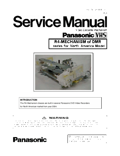
>> Download panasonic_r4_vcr-mechanika documenatation <<
Text preview - extract from the document
                                                                                                              Order NO. VR0404003C1
                                                                                                                                        B24


                                                                                               Video Cassette Mechanism


                                                              R4-MECHANISM of DMR
                                                            series for North America Model


         INTRODUCTION
         The R4-Mechanism chassis are built in several Panasonic DVD Video Recorders
         for North American market from year 2004.


This service information is designed for experienced repair technicians only and is not designed for use by the general public.
It does not contain warnings or cautions to advise non-technical individuals of potential dangers in attempting to service a product.
Products powered by electricity should be serviced or repaired only by experienced professional technicians. Any attempt to service
or repair the product or products dealt with in this service information by anyone else could result in serious injury or death.


                                                                                          2004 Matsushita Electric Industrial Co., Ltd.
                                                                                    All rights reserved. Unauthorized copying and
                                                                                    distribution is violation of law.


                                                                     1
                                                                        CONTENTS
CONTENTS.......................................................................................................................................................... 2
1. OUTLINE OF R4 MECHANISM ....................................................................................................................... 4
     1.1. FEATURES................................................................................................................................................ 4
     1.2. THE TAPE TRANSPORT PATH ................................................................................................................ 4
     1.3. PARTS NAME OF R4-MECHANISM......................................................................................................... 5
     1.4. NEW DD CYLINDER UNIT ....................................................................................................................... 7
     FEATURE ......................................................................................................................................................... 7
     1.5. PG SHIFTER AUTOMATIC ADJUSTMENT.............................................................................................. 8
        1.5.1. ADJUSTMENT PROCEDURE............................................................................................................ 8
        1.5.2. (VHS) X-VALUE & LINEARITY (P2 and P3 Posts) ADJUSTMENT ................................................... 9
2.      REMOVAL OF CASSETTE TAPE............................................................................................................... 10
     2.1. Removal by compulsory unloading. ........................................................................................................ 10
     2.2. Removal by manual operation by rotating the Loading Motor with the batteries.................................... 10
     Take out Cassette Tape manually after removing the mechanism..................................................................11
3. REMOVAL OF CASSETE HOLDER UNIT & MECHANISM CHASSIS......................................................... 12
     3.1. Top Case.................................................................................................................................................. 12
     3.2. Front Panel .............................................................................................................................................. 12
     3.3. VTR Mechanism Unit............................................................................................................................... 13
        3.3.1. Caution for attaching VTR Mechanism Unit ..................................................................................... 13
     3.4. REMOVAL OF CASSETTE HOLDER UNIT............................................................................................ 14
4. DISASSEMBLY /ASSEMBLY METHOD FOR MECHANISM ........................................................................ 15
     4-1. DISASSEMBLY OF MECHANISM .......................................................................................................... 15
4.2. ASSEMBLY AND PHASE ADJUSTMENT OF MECHANISM..................................................................... 19
5. MECHANICAL ADJUSTMENT PROCEDURE............................................................................................... 28
     5.1. P2 AND P3 POST ADJUSTMENT (PREADJUSTMENT)....................................................................... 28
     5.2. TAPE INTERCHANGEABILITY ADJUSTMENT..................................................................................... 28
        5.2.1. P2 AND P3 POST ADJUSTMENT.................................................................................................... 28
        5.2.2. ADJUSTMENT OF P4 POST............................................................................................................ 30
        5.2.3. HEIGHT ADJUSTMENT OF A/C HEAD ........................................................................................... 31
        5.2.4. FINE-ADJUSTMENT OF A/C HEAD ................................................................................................ 31
        5.2.5. ADJUSTMENT OF X-VALUE (PREADJUSTMENT) ........................................................................ 31
        5.2.6. FINE-ADJUSTMENT OF X-VALUE .................................................................................................. 32
Servicing Fixture & Tools.................................................................................................................................... 33
6. SERVICE INFORMATION DISPLAY ............................................................................................................. 34
     6.1. Purpose of Service Information Display .................................................................................................. 34
     6.2. Turning on Service Information Display................................................................................................... 34
7. SELF- DIAGNOSIS INDICATION DISPLAY .................................................................................................. 36
Example of Error Indication on the FIP .............................................................................................................. 36
Division of Management..................................................................................................................................... 36
     7.1. TABLE OF DETECTING CONDITION AND MOVEMENT OF MECHANISM IN DETECTING OF THE

                                                                                   2
   SELF-DIAGNOSIS FUNCTION...................................................................................................................... 37
   .7.2. MEMORY OF THE SELF-DIAGNOSIS HISTORY AND THE SUPPLEMENTARY DATA.................... 40
      7.2.1. Error Number and Supplementary Data ........................................................................................... 40
      7.2.2. Condition for memorizing of the self-diagnosis history..................................................................... 41
      7.2.3. Condition for clearing the self-diagnosis history............................................................................... 41
      7.2.4. Indication of the self-diagnosis history. ............................................................................................. 41
   7.3. MEMORY TIMING FOR ERROR NO. F03 & F04................................................................................... 42
      7.3.1. Mechanism lock during the mechanism initial operation cause of a mechanism lock..................... 42
      7.3.2. The mechanism lock during the mechanism initial operation with returning from an Error or the
      power failure................................................................................................................................................ 42
   7.4. ANALIZING PROCEDURE FOR MECHANISM ERROR........................................................................ 42
9. TIMING CHART OF MODE SW..................................................................................................................... 44
10. SYSTEM CONTROL CIRCUIT .................................................................................................................... 45
   10.1. MODE TRANSITION............................................................................................................................. 45
      10.1.1. Basic mode action (without EDIT function)..................................................................................... 45
      10.1.2. Basic mode action (with EDIT function).......................................................................................... 45
   10.2. BASIC ACTION IN MECHANISM ......................................................................................................... 46
      10.2.1. Position SW and main action at each position............................................................................... 46
      10.2.2. Mechanism initializing action at each position................................................................................ 46
      10.2.3. Mechanism action in sand-by condition after cassette is inserted ................................................. 46
      10.2.4. Mechanism action in EJECT operation .......................................................................................... 46
   10.3. SUPPLY AND TAKE-UP SENSORS .................................................................................................... 47
      10.3.1. Detection timing .............................................................................................................................. 47
      10.3.2. Sensitivity of detecting the start and end edges of tape................................................................. 47
      10.3.3. Action after start and end edges are detected................................................................................ 47
   10.4. SAFETY TAB SWITCH ......................................................................................................................... 47
   10.5. SAFETY TIMER..................................................................................................................................... 48
      10.5.1. Holding time of special playback and stand-by mode .................................................................... 48
      10.5.2. Detecting mechanism lock during mode shift................................................................................. 48
      10.5.3. Detecting reel lock .......................................................................................................................... 48
      10.5.4. Detecting cylinder lock.................................................................................................................... 49
   10.6. Automatic features ................................................................................................................................. 49
11. MOTOR DRIVE SECTION ........................................................................................................................... 50
   11.1. CAPSTAN DRIVE CIRCUIT .................................................................................................................. 50
      11.1.1. R4 Mechanism employs Full time Full-wave drive method ............................................................ 50
      11.1.2. R4 Mechanism employs PWM (Pulse Width Motor) as Capstan Motor Drive Signal in REC or
      PLAYBACK mode ....................................................................................................................................... 51
   11.2.CYLINDER DRIVE AND LOADING MOTOR DRIVE CIRCUIT ............................................................. 53


                                                                                 3
 1. OUTLINE OF R4 MECHANISM
 1.1. FEATURES
      Item                                           R4-Mechanism
      Pieces of the Components                       125 pieces
      DD Cylinder                                    Corresponding heads: 2 ~ 10ch
                                                     Weight: 76%
      FF/REW speed                                   600 / 400 times
      Capstan drive IC, Cylinder drive IC, Loading   All new ICs
      motor drive IC
      Capstan Unit                                   PWM Drive
      Cylinder Unit                                  RDD
      Phase adjustment place                         5 places
      Slot in unit                                   Sector gear drive


1.2. THE TAPE TRANSPORT PATH

                   S-INCLIND POST               T-INCLIND POST
         P2 POST                                                    P3 POST

                                     CYLINDER


                   FE HEAD
                                                          AE HEAD

    TENSIO         P0
                                                     A/C HEAD                             PINCH ROLLER
    N POST
                    C1
                                                            P4 POST                          C3


       C2
                                                                              CAP                 C4
                                                                                     P5


                                                 Fig.M1


                                                        4
1.3. PARTS NAME OF R4-MECHANISM


                             Fig.M2


                               5
Ref. No.   Part Name                       Ref. No.   Part Name
101        CYLINDER UNIT                   143        SCREW
102        CAPSTAN UNIT                    143        SCREW
103        FE HEAD                         144        SCREW
104        TENSION ARM BOSH                144        SCREW
105        INTERMEDIATE GEAR               144        SCREW
106        MAIN CAM GEAR                   145        SCREW
107        IDLER GEAR                      145        SCREW
107        IDLER GEAR                      146        SCREW
108        CHANGE GEAR                     147        SCREW
109        REEL TABLE                      148        SCREW
109        REEL TABLE                      148        SCREW
110        CAPSTAN BELT                    149        WASHER
111        LOADING MOTOR UNIT              150        WASHER
112        CHANGE GEAR SPRING              151        WASHER
113        WORM SHAFT HOLDER               152        WASHER
114        OPENER PIECE
115        LED PRISM
116        MAIN LEVER
117        PINCH CHARGE ARM
118        IDLER ARM
119        P4 CAP
120        SUPPLY SHAFT HOLDER UNIT
121        TAKE UP SHAFT HOLDER UNIT
122        AC HEAD UNIT
122-1      SCREW
122-1      SCREW
122-2      SCREW
124        SUPPLY LOADING ARM UNIT
125        TAKE UP LOADING ARM UNIT
126        PINCH ARM UNIT
127        P5 ARM UNIT
128        TENSION ARM UNIT
128-1      TENSION SPRING
129        SUPPLY BRAKE ARM UNIT
130        TAKE UP BRAKE ARM UNIT
130-1      TAKE UP BRAKE SPRING
131        CHANGE LEVER UNIT
132        CENTRE CLUTCH UNIT
133        TORQUE CLUTCH UNIT
134        TOP PLATE
135        SIDE PLATE (L)
136        SIDE PLATE
◦ Jabse Service Manual Search 2026 ◦ Jabse Pravopis ◦ onTap.bg ◦ Other service manual resources online : Fixya ◦ eServiceinfo