Service Manuals, User Guides, Schematic Diagrams or docs for : . Car Manuals Acura 3.5RL 1996-2004 Approved srm RL9604D23016A
<< Back | HomeMost service manuals and schematics are PDF files, so You will need Adobre Acrobat Reader to view : Acrobat Download Some of the files are DjVu format. Readers and resources available here : DjVu Resources
For the compressed files, most common are zip and rar. Please, extract files with Your favorite compression software ( WinZip, WinRAR ... ) before viewing. If a document has multiple parts, You should download all, before extracting.
Good luck. Repair on Your own risk. Make sure You know what You are doing.
Image preview - the first page of the document
>> Download RL9604D23016A documenatation <<
Text preview - extract from the document
Main Menu Table of Contents
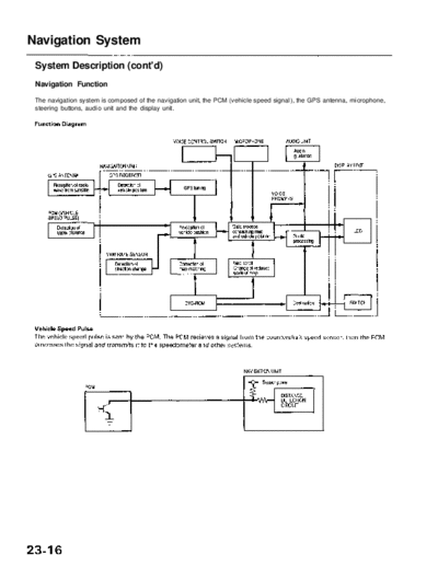
Navigation System
System Description (cont'd)
Navigation Function
The navigation system is composed of the navigation unit, the PCM (vehicle speed signal), the GPS antenna, microphone,
steering buttons, audio unit and the display unit.
Main Menu Table of Contents
Yaw Rate Sensor
The yaw rate sensor (located in the navigation unit) detects the direction change (angular speed) of the vehicle. The sen-
sor is an oscillation gyro built into the navigation unit.
Sensor Element Structure
The sensor element is shaped like a tuning fork, and it consists of the piezoelectric parts, the metal block, and the support
pin. There are four piezoelectric parts: one to drive the oscillators, one to monitor and maintain the oscillation at a regular
frequency, and two to detect angular velocity. The two oscillators, which have a 90-degree twist in the center, are connect-
ed at the bottom by the metal block and supported by the support pin. A detection piezoelectric part is attached to the top
of each oscillator. The driving piezoelectric part is attached to the bottom of one oscillator, and the monitoring piezoelec-
tric part is attached to the bottom of the other oscillator.
Oscillation Gyro Principles
The piezoelectric parts have "electric/mechanical transfer characteristics." They bend vertically when voltage is applied to
both sides of the parts, and voltage is generated between both sides of the piezoelectric parts when they are bent by an
external force. The oscillation gyro functions by utilizing this characteristic of the piezoelectric parts and "Coriolis force."
(Coriolis force deflects moving objects as a result of the earth's rotation.) In the oscillation gyro, this force moves the sen-
sor element when angular velocity is applied.
Operation
1. The driving piezoelectric part oscillates the oscillator by repeatedly bending and returning when an AC voltage of 6 kHz
is applied to the part, The monitoring-side oscillator resonates because it is connected to the driving-side oscillator by
the metal block.
2. The monitoring piezoelectric part bends in proportion to the oscillation and outputs voltage (the monitor signal). The
navigation unit control circuit controls the drive signal to stabilize the monitor signal.
3. When the vehicle is stopped, the detecting piezoelectric parts oscillate right and left with the oscillators, but no signal is
output because the parts are not bent (no angular force).
4. When the vehicle turns to the right, the sensor element moves in a circular motion with the right oscillator bending for-
ward and the left oscillator bending rearward. The amount of forward/rearward bend varies according to the angular
velocity of the vehicle.
5. The detecting piezoelectric parts output voltage (the yaw rate signal) according to the amount of bend. The amount of
vehicle direction change is determined by measuring this voltage.
Main Menu Table of Contents
Navigation System
System Description (cont'd)
Global Positioning System (GPS)
The Global Positioning System (GPS) enables the navigation system to determine the current position of the vehicle by
utilizing the signals transmitted from the satellites in orbit around the earth. The satellites transmit the satellite identifica-
tion signal, orbit information, transmission time signal, and other information. When the GPS receiver receives a signal
from three or more satellites simultaneously, it calculates the current position of the vehicle based on the distance to each
satellite and the satellite positions on their respective orbits.
Position detection Image with GPS satellite
Precision of GPS
The precision of the GPS varies according to the number of satellites from which electric waves are received and the con-
trol condition. The precision is indicated by the color of the GPS icon shown on the upper right of the display.
GPS Antenna
The GPS antenna amplifies and transmits the signals received from the satellites to the GPS receiver.
GPS Receiver
The GPS receiver is built in the navigation unit. It calculates the vehicle position by receiving the signal from the GPS
antenna. The vehicle position and signal reception condition is transmitted from the GPS receiver to the navigation control
unit to adjust vehicle position.
Main Menu Table of Contents
Navigation Unit
The navigation unit calculates the vehicle position and guides you to the destination. The unit performs map matching
correction, GPS correction, and distance tuning. It also controls the menu functions and the DVD-ROM drive, and inter-
prets voice commands. With control of all these items, the navigation unit makes the navigation picture signal, then it
transmits the signal to the display unit and audio driving instructions to the audio unit.
Calculation of Vehicle Position
The navigation unit calculates the vehicle position (the driving direction and the current position) by receiving the direc-
tional change signals from the yaw rate sensor and the travel distance signals from the vehicle speed pulse (VSP) sensor.
Map Matching Tuning
The map matching tuning is accomplished by indicating the vehicle position on the roads on the map. The map data
transmitted from the DVD-ROM is checked against the vehicle position data, and the vehicle position is indicated on the
nearest road. Map matching tuning does not occur when the vehicle travels on a road not shown on the map, or when the
vehicle position is far away from a road on the map.
GPS Tuning
The GPS tuning is accomplished by indicating the vehicle position as the GPS's vehicle position. The navigation unit com-
pares its calculated vehicle position data with the GPS vehicle position data. If there is a large difference between the two,
the indicated vehicle position is adjusted to the GPS vehicle position.
Distance Tuning
The distance tuning reduces the difference between the travel distance signal from the VSP and the distance data on the
map. The navigation unit compares its calculated vehicle position data with the GPS vehicle position data. The navigation
unit then decreases the tuning value when the vehicle position is always ahead of the GPS vehicle position, and it increas-
es the tuning value when the vehicle position is always behind the GPS vehicle position.
Route Guidance
The navigation unit can calculate different routes to a selected destination. You have five options:
◦ Jabse Service Manual Search 2026 ◦ Jabse Pravopis ◦ onTap.bg ◦ Other service manual resources online : Fixya ◦ eServiceinfo