Service Manuals, User Guides, Schematic Diagrams or docs for : . Car Manuals Acura 3.5RL 1996-2004 Approved srm RL9604S05003A

<< Back | Home

Most service manuals and schematics are PDF files, so You will need Adobre Acrobat Reader to view : Acrobat Download Some of the files are DjVu format. Readers and resources available here : DjVu Resources
For the compressed files, most common are zip and rar. Please, extract files with Your favorite compression software ( WinZip, WinRAR ... ) before viewing. If a document has multiple parts, You should download all, before extracting.
Good luck. Repair on Your own risk. Make sure You know what You are doing.


Image preview - the first page of the document
RL9604S05003A


>> Download RL9604S05003A documenatation <<

Text preview - extract from the document
                Main Menu                 Table of Contents


Engine Removal/Installation
 Removal
                                                                 3.     Make sure you have the anti-theft code for the radio,
      Make sure jacks and safety stands are placed properly            then write down the frequencies for the radio's pre-
      and hoist brackets are attached to the correct positions         set buttons.
      on the engine.
      Make sure the vehicle will not roll off stands and fall    4.     Disconnect the battery negative terminal first, then
      while you are working under it.                                  the positive terminal.

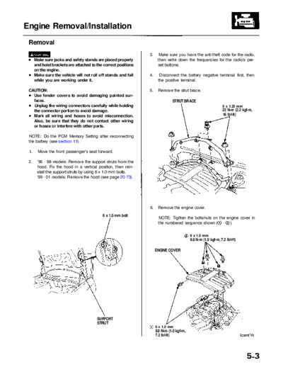
 CAUTION:                                                        5.    Remove the strut brace.
   Use fender covers to avoid damaging painted sur-
   faces.                                                                       STRUT BRACE
   Unplug the wiring connectors carefully while holding                                                           8 x 1.25 mm
   the connector portion to avoid damage.                                                                         22 N-m (2.2 kgf-m,
   Mark all wiring and hoses to avoid misconnection.                                                              16 Ibf-ft)
   Also, be sure that they do not contact other wiring
   or hoses or interfere with other parts.

 NOTE: Do the PCM Memory Setting after reconnecting
 the battery (see section 11).

 1.     Move the front passenger's seat forward.

 2.    '96 - 98 models: Remove the support struts from the
       hood. Fix the hood in a vertical position, then rein-
       stall the support struts by using 6 x 1.0 mm bolts.
       '99 - 01 models: Remove the hood (see page 20-73).


                                                                 6.    Remove the engine cover.
                                            6 x 1.0 mm bolt
                                                                       NOTE: Tighten the bolts/nuts on the engine cover in
                                                                       the numbered sequence shown (     - ).


                                                                                            6 x 1.0 mm
                                                                                            9.8 N-m (1.0 kgf-m, 7.2 Ibf-ft)

                                                                      ENGINE COVER


                                         SUPPORT
                                         STRUT
                                                                      6 x 1.0 mm
                                                                      9.8 N-m (1.0 kgf-m,
                                                                      7.2 Ibf-ft)
                   Main Menu            Table of Contents


Engine Removal/Installation
 Removal (cont'd)
 7.     Remove the intake air duct and air cleaner housing       10. Raise the coolant reservoir, then remove the battery
        assembly.                                                    and battery base.

                                            6 x 1.0 mm                                                 6 x 1.0 mm
                                            12 N-m (1.2 kgf-m,                                         12 N-m (1.2 kgf-m,
                                            8.7 Ibf-ft)                                                8.7 Ibf-ft)
                                                                         BATTERY
                                                                         BASE
                                                 INTAKE AIR
                                                 DUCT


        AIR CLEANER
        HOUSING
        ASSEMBLY


 8.     Remove the throttle cover.

 9.     Remove the throttle cable and cruise control cable
        by loosening the locknuts, then slip the cable ends
        out of the accelerator linkage.
                                                                 11. Remove the relay box, ground cable and engine
        NOTE:                                                        wire harness clamps.
          Take care not to bend the cables when removing
          them. Always replace any kinked cable with a
          new one.                                                     ENGINE WIRE               6 x 1.0 mm
          Adjust the throttle cable when installing (see               HARNESS CLAMP             12 N-m (1.2 kgf-m, 8.7 Ibf-ft)
          section 11).
          Adjust the cruise control cable when installing
          (see section 4).
      6 x 1.0 mm
      12 N-m (1.2 kgf-m,                THROTTLE COVER
      8.7 Ibf-ft)

                                                 THROTTLE
                                                 CABLE


                                                   CRUISE
                                                   CONTROL
                                                   CABLE


                                                                                                                 GROUND
                                                                                                                 CABLE

                                             LOCKNUTS                  RELAY BOX

                           ADJUSTING
                           NUTS
               Main Menu             Table of Contents


12. Remove the vacuum hose, then remove the clamp        14. Disconnect the engine wire harness connector on
    from the under-hood fuse/relay box.                      the left side of the engine compartment.

                                                         15. Remove the connector and engine wire harness
                                                             clamp.
      VACUUM
      HOSE                                CLAMP
                                                                    CONNECTOR
                                                                                                         ENGINE WIRE
                                                                                                         HARNESS
                                                                                                         CONNECTOR
                                                             CLAMP


                                                           6 x 1.0 mm
                                                           12 N-m (1.2 kgf-m, 8.7 Ibf-ft)


                                                         16. Relieve fuel pressure by loosening the service bolt
                                                             on the fuel filter about one turn (see section 11).

13. Remove the alternator and battery cables from the                      Do not smoke while working on the
    under-hood fuse/relay box, then remove the under-         fuel system. Keep open flame and sparks away from
    hood fuse/relay box.                                      the work area. Drain fuel only into an approved
                                                              container.
                 ALTERNATOR
                 CABLE
                                BATTERY                   17. Remove the fuel feed hose and fuel return hose.
 6 x 1.0 mm                     CABLE
 12 N-m (1.2 kgf-m,
 8.7 Ibf-ft)                                                                                27 N-m (2.8 kgf-m,
                                                         SERVICE BOLT                       20 Ibf-ft)
                                                         12 N-m (1.2 kgf-m, 8.7 Ibf-ft)                WASHERS
                                                                                                       Replace.


                                                         WASHER
                                                         Replace.


                                           UNDER-HOOD
                                           FUSE/RELAY
                                           BOX


                                                              FUEL FEED
                                                              HOSE                             FUEL RETURN
                                                                                               HOSE
           Main Menu              Table of Contents


Engine Removal/Installation
 Removal (cont'd)
 18. Remove the evaporative emission (EVAP) canister   20. Disconnect the connector, then remove the control
     hose and brake booster vacuum hose.                   box.

                                                                  6 x 1.0 mm
                                   BRAKE BOOSTER                  12 N-m (1.2 kgf-m,
                                   VACUUM HOSE                    8.7 Ibf-ft)


     EVAP CONTROL
     CANISTER HOSE                                                                         CONTROL
                                                                CONNECTOR                  BOX


                                                       21. Disconnect the engine wire harness connectors on
 19. Disconnect the transmission sub-harness connec-       the right side of the engine compartment.
     tor, and remove the wire harness clamp.


             WIRE HARNESS
             CLAMP                   TRANSMISSION
                                     SUB-HARNESS
                                     CONNECTOR


                                                               ENGINE WIRE
                                                               HARNESS CONNECTOR
           Main Menu               Table of Contents


22. Disconnect the spark plug voltage detection module   24. Loosen the mounting bolt, lock bolt and adjusting
    connector, and remove the engine ground cables.          rod, then remove the alternator belt.


       6 x 1.0 mm
       12 N-m (1.2 kgf-m,               GROUND                               ADJUSTING             LOCK BOLT
                                                                             ROD                   8 x 1.25 mm
       8.7 Ibf-ft)                      CABLES
                                                                                                   22 N-m (2.2 kgf-m,
                                                                                                   16 Ibf-ft)


                                                          ALTERNATOR                     MOUNTING BOLT
                                                          BELT                           10 x 1.25 mm
                                                                                         44 N-m (4.5 kgf-m,
                                                                                         33 Ibf-ft)
    SPARK PLUG VOLTAGE
    DETECTION MODULE
    CONNECTOR                                            25. Loosen the idler pulley center nut and adjusting
                                                             bolt, then remove the air conditioning (A/C) com-
23. Remove the vacuum hoses.                                 pressor belt.


                                                                           ADJUSTING
                                                                           BOLT                  IDLER PULLEY
                                                                                                 CENTER NUT
                                                                                                 10 x 1.25 mm
                                                                                                 44 N-m (4.5 kgf-m,
                                                                                                 33 Ibf-ft)


                                                          A/C COMPRESSOR
                                                          BELT
                                 VACUUM
                                 HOSES
              Main Menu               Table of Contents


Engine Removal/Installation
 Removal (cont'd)
 26. Disconnect the power steering pressure (PSP) switch       29. Remove the radiator cap.
     connector.
                                                                                Use care when removing the radiator
         ADJUSTING                        LOCKNUT                  cap to avoid scalding by hot coolant or steam.
         BOLT                             8 x 1.25 mm
                                          22 N-m (2.2 kgf-m,   30. Raise the hoist to full height.
                                          16 Ibf-ft)
                                                               31. Remove the front tires/wheels and splash shield.


   PSP SWITCH
   CONNECTOR
                                               P/S PUMP
                                               BELT
             MOUNTING BOLT
             10 x 1.25 mm
             44 N-m (4.5 kgf-m,
             33 Ibf-ft)


 27. Remove the adjusting bolt, locknut and mounting
     bolt, then remove the power steering (P/S) pump                                                   SPLASH
     belt and pump.                                                                                    SHIELD
                                                                 6 x 1.0 mm
     NOTE: Do not disconnect the P/S hoses.                      9.8 N-m (1.0 kgf-m, 7.2 Ibf-ft)

 28. Pull the carpet back underneath the front passen-
     ger's seat to expose the secondary heated oxygen          32. Drain the engine coolant (see page 10-5). Loosen
     sensor (secondary HO2S) connector, then discon-               the drain plug in the radiator.
     nect the secondary HO2S connector.
                 SECONDARY                                     33. Drain the automatic transmission fluid (ATF). Reinstall
                 HO2S CONNECTOR                                    the drain plug using a new washer (see section 14).

                                                               34. Drain the differential oil. Reinstall the drain plug
                                                                   using a new washer (see section 15).

                                                               35. Drain the engine oil. Reinstall the drain bolt using a
                                                                   new washer (see page 8-4).

                                                               36. Remove the damper forks (see section 18).

                                                               37. Disconnect the suspension lower arm ball joints
                                                                   (see section 18).

                                                               38. Remove the driveshafts (see section 16).

                                                                    NOTE: Coat all precision finished surfaces with
                                                                    clean engine oil. Tie plastic bags over the driveshaft
                                                                    ends.
            Main Menu                Table of Contents


39. Disconnect the compressor clutch connector, then       41. Remove the transmission stop collars.
    remove the A/C compressor. Do not disconnect the
    A/C hoses.                                             42. Remove exhaust pipe A.

                                                                          SELF-LOCKING NUT
                                                                          8 x 1.25 mm
                                                                          22 N-m (2.2 kgf-m, 16 Ibf-ft)
                                     COMPRESSOR CLUTCH                    Replace.
                                     CONNECTOR                                                                  GASKETS
                                                                                                                Replace.


                                                           GASKET
                                                           Replace.


                                                           EXHAUST
                                                           PIPE A                                         SELF-LOCKING NUT
           A/C COMPRESSOR
                                                                                                          10 x 1.25 mm
                                                            SELF-LOCKING NUT                              54 N-m (5.5 kgf-m,
                                8 x 1.25 mm                 10 x 1.25 mm                                  40 Ibf-ft)
                                22 N-m (2.2 kgf-m,          54 N-m (5.5 kgf-m,                            Replace.
                                16 Ibf-ft)                  40 Ibf-ft)
                                                            Replace.
                                                                                                     TRANSMISSION STOP
                                                                              10 x 1.25 mm           COLLAR
                                                                              38 N-m (3.9 kgf-m,
                                                                              28 Ibf-ft)


40. Disconnect the vehicle speed sensor (VSS) connector,   43. Remove the wire harness cover and grommet, then
    then remove the VSS/power steering speed sensor.           remove the three way catalytic converter (TWC).
    Do not disconnect the fluid hoses.
                                                             SELF-LOCKING NUT
                                                             10 x 1.25 mm                                   WIRE HARNESS
                                                                                         GROMMET
                                                             33 N-m (3.4 kgf-m,                             COVER
  6 x 1.0 mm              VSS CONNECTOR                      25 Ibf-ft)
  12 N-m (1.2 kgf-m,                                         Replace.
  8.7 Ibf-ft)


                                                               GASKET
                                                               Replace.
          VSS/POWER STEERING
          SPEED SENSOR                                                              TWC
                                                                                                          6 x 1.0 mm
                                                                                                          9.8 N-m (1.0 kgf-m,
                                                                                                          7.2 Ibf-ft)
              Main Menu                  Table of Contents


Engine Removal/Installation
 Removal (cont'd)
 44. Remove the heat shield.                                         50. Lower the hoist.

                                                                     51. Remove the upper and lower radiator hoses.


                                                  Loosen these
                                                  bolts.


                                             HEAT
                                             SHIELD
       6 x 1.0 mm                                                                                      UPPER RADIATOR
      9.8 N-m (1.0 kgf-m, 7.2 Ibf-ft)                                                                  HOSE
 45. Remove the ATF cooler hoses. Plug the ATF cooler                       LOWER RADIATOR
     hoses and lines.                                                       HOSE
                          LOCKNUT
                          16 N-m (1.6 kgf-m, SHIFT CABLE
                          12 Ibf-ft)         HOLDER
       6 x 1.0 mm
       12 N-m (1.2 kgf-m
       8.7 Ibf-ft)                                                   52. Remove the radiator assembly (see page 10-4).

                                                                     53. Remove the heater hoses.


     SHIFT CABLE
     COVER                                      6 x 1.0 mm
                                                12 N-m (1.2 kgf-m,
                                                8.7 Ibf-ft)

        CONTROL
        LEVER                   ATF COOLER
                                HOSES


 46. Remove the shift cable cover mounting bolts, then
     remove the shift control solenoid valve/linear sole-
     noid harness connector from the shift cable cover.

 47. Remove the shift cable cover from the transmission                                                   HEATER
     housing.                                                                                             HOSES

 48. Remove the shift cable with shift cable holder from
     the shift cable holder base.

 49. Remove the control lever from the control shaft.
           Main Menu                 Table of Contents


54. Attach the chain hoist to the engine.

                                                         FUEL PRESSURE REGULATOR
                                                         29 N-m (3.0 kgf-m, 22 Ibf-ft)
                                                         NOTE: Loosen the locknut on the
                                                         fuel pressure regulator, then turn
                                                         the fuel pressure regulator 180


◦ Jabse Service Manual Search 2026 ◦ Jabse PravopisonTap.bg ◦ Other service manual resources online : FixyaeServiceinfo