Service Manuals, User Guides, Schematic Diagrams or docs for : . Car Manuals Acura 3.5RL 1996-2004 Approved srm RL9604S05014A

<< Back | Home

Most service manuals and schematics are PDF files, so You will need Adobre Acrobat Reader to view : Acrobat Download Some of the files are DjVu format. Readers and resources available here : DjVu Resources
For the compressed files, most common are zip and rar. Please, extract files with Your favorite compression software ( WinZip, WinRAR ... ) before viewing. If a document has multiple parts, You should download all, before extracting.
Good luck. Repair on Your own risk. Make sure You know what You are doing.


Image preview - the first page of the document
RL9604S05014A


>> Download RL9604S05014A documenatation <<

Text preview - extract from the document
                  Main Menu               Table of Contents


Engine Removal/Installation
   Installation
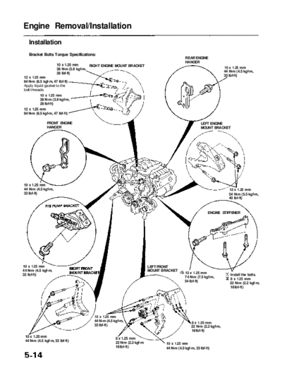
   Bracket Bolts Torque Specifications:
                                                                                             REAR ENGINE
                                                                                             HANGER
                     10 x 1.25 mm       RIGHT ENGINE MOUNT BRACKET
                     38 N-m (3.9 kgf-m,                                                                               10 x 1.25 mm
                     28 Ibf-ft)                                                                                       44 N-m (4.5 kgf-m,
12 x 1.25 mm                                                                                                          33 Ibf-ft)
64 N-m (6.5 kgf-m, 47 Ibf-ft)
Apply liquid gasket to the
bolt threads.
          10 x 1.25 mm
          38 N-m (3.9 kgf-m,
          28 Ibf-ft)
12 x 1.25 mm
64 N-m (6.5 kgf-m, 47 Ibf-ft)

               FRONT ENGINE                                                                             LEFT ENGINE
               HANGER                                                                                   MOUNT BRACKET


10 x 1.25 mm
44 N-m (4.5 kgf-m,                                                                                                       12 x 1.25 mm
33 Ibf-ft)                                                                                                               54 N-m (5.5 kgf-m,
                                                                                                                         40 Ibf-ft)


                                                                                                            ENGINE STIFFENER


10 x 1.25 mm                                                             LEFT FRONT
44 N-m (4.5 kgf-m,                                                       MOUNT BRACKET
                                                                                             12 x 1.25 mm
33 Ibf-ft)                                                                                                               Install the bolts.
                                                                                             74 N-m (7.5 kgf-m,
                                                                                                                         8 x 1.25 mm
                                                                                             54 Ibf-ft)
                                                                                                                         22 N-m (2.2 kgf-m,
                                                                                                                         16 Ibf-ft)


                                        10 x 1.25 mm
                                        44 N-m (4.5 kgf-m,                                       8 x 1.25 mm
                                        33 Ibf-ft)                                               22 N-m (2.2 kgf-m,
                                                                                                 16 Ibf-ft)
 10 x 1.25 mm                                        8 x 1.25 mm
 44 N-m (4.5 kgf-m, 33 Ibf-ft)
                                                     22 N-m (2.2 kgf-m           10 x 1.25 mm
                                                     16 Ibf-ft)                  44 N-m (4.5 kgf-m, 33 Ibf-ft)
             Main Menu                       Table of Contents


Engine Installation:                                             3.    Tighten the nut on the right engine mount bracket,
                                                                       then install the vacuum hose.
Install the engine in the reverse order of removal.
Reinstall the mount bolts/nuts in the following sequence.                                             12 x 1.25 mm
Failure to follow these procedures may cause excessive                                                64 N-m (6.5 kgf-m,
noise and vibration, and reduce bushing life.                                                         47 Ibf-ft)


CAUTION: Take care not to damage the rear beam when
installing the engine/transmission assembly.

                                                                      VACUUM
                                                                      HOSE


         REAR BEAM
         Install the engine so that
         the rear beam does not
         hit the transmission.


1.    Install the transmission mount bracket, then tighten
     the mounting bolts.
                                                TRANSMISSION     4.    Tighten the nut on the left engine mount bracket,
               TRANSMISSION                     MOUNT                  then install the vacuum hose.
               MOUNT BRACKET
                                                                                                        12 x 1.25 mm
                                                                                                        64 N-m (6.5 kgf-m,
                                                                                                        47 Ibf-ft)


                                      10 x 1.25 mm                                                        VACUUM
                                      38 N-m (3.9 kgf-m,                                                  HOSE
                                      28 Ibf-ft)

2.   Install the transmission mount. Do not tighten the
     bolt.
               Main Menu                 Table of Contents


Engine Removal/Installation
 Installation (cont'd)
 5.   Install the transmission beam, then tighten the bolts     7.   Tighten the right front mount mounting bolt.
      in the numbered sequence shown (           ).


       12 x 1.25 mm                                                                                 12 x 1.25 mm
       54 N-m (5.5 kgf-m,                                                                           74 N-m (7.5 kgf-m,
       40 Ibf-ft)                                                                                   52 Ibf-ft)
                                           10 x 1.25 mm
                                           38 N-m (3.9 kgf-m,
                                           28 Ibf-ft)


                                                                8.   Do the following checks and adjustments:

                                 10 x 1.25 mm                           Check that the set rings on the ends of the drive-
                                 38 N-m (3.9 kgf-m,
                                 28 Ibf-ft)
                                                                        shaft and intermediate shaft click into place.
                                                                        CAUTION: Use new set rings.
                                                                        Adjust the shift cable (see section 14).
 6.   Tighten the left front mount mounting bolt.                       Adjust the throttle cable (see section 11).
                                                                        Adjust the cruise control cable (see section 4).
                                                                        Refill the engine with engine oil (see page 8-4).
                                                                        Refill the transmission with ATF (see section 14).
                                                                        Refill the differential with differential oil (see
            12 x 1.25 mm
            74 N-m (7.5 kgf-m,                                          section 15).
            52 Ibf-ft)                                                  Refill the radiator with engine coolant (see page
                                                                        10-5).
                                                                        Bleed air from the cooling system at the bleed
                                                                        bolt with the heater valve open (see page 10-5).
                                                                        Clean the battery posts and cable terminals with
                                                                        sandpaper, assemble them, then apply grease to
                                                                        prevent corrosion.
                                                                        Inspect for fuel leakage (see section 11).
                                                                        -- After assembling all fuel line parts, turn on
                                                                           the ignition switch (do not operate the starter)
                                                                           so that the fuel pump operates for approxi-
                                                                           mately 2 seconds and pressurizes the fuel
                                                                           line.
                                                                        -- Repeat this operation 2 or 3 times, then check
                                                                           for fuel leakage at any point in the fuel line.
                                                                        Enter the anti-theft code for the radio, then enter
                                                                        the customer's radio station presets.
           Main Menu                Table of Contents


Mount and Bracket Bolts/Nuts Torque Value Specifications:
10 x 1.25 mm bolts/nuts: 38 N-m (3.9 kgf-m, 28 Ibf-ft)


             RIGHT ENGINE MOUNT


                                                                               LEFT ENGINE MOUNT


      RIGHT FRONT MOUNT


                                                            LEFT FRONT MOUNT


◦ Jabse Service Manual Search 2026 ◦ Jabse PravopisonTap.bg ◦ Other service manual resources online : FixyaeServiceinfo