Service Manuals, User Guides, Schematic Diagrams or docs for : . Car Manuals Acura 3.5RL 1996-2004 Approved srm RL9604S06010A
<< Back | HomeMost service manuals and schematics are PDF files, so You will need Adobre Acrobat Reader to view : Acrobat Download Some of the files are DjVu format. Readers and resources available here : DjVu Resources
For the compressed files, most common are zip and rar. Please, extract files with Your favorite compression software ( WinZip, WinRAR ... ) before viewing. If a document has multiple parts, You should download all, before extracting.
Good luck. Repair on Your own risk. Make sure You know what You are doing.
Image preview - the first page of the document
>> Download RL9604S06010A documenatation <<
Text preview - extract from the document
Main Menu Table of Contents
Timing Belt and Balancer Belt
Installation
Install the timing belt and balancer belt in the reverse
order of removal; only key points are described here.
CAUTION: Do not rotate the crankshaft pulley or cam-
shaft pulleys with the timing belt removed. The pistons
may hit the valves and cause damage.
NOTE: When installing only the balancer belt, go to step
12.
1. Remove the spark plugs.
2. Remove the balancer belt drive pulley and timing
belt guide plate (see page 6-4).
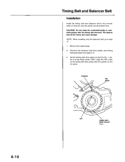
3. Set the tinning belt drive pulley so that the No. 1 pis-
ton is at top dead center (TDC). Align the TDC mark
on the timing belt drive pulley with the pointer on the
oil pump.
POINTER
TDC
MARK
KEY
TIMING BELT
DRIVE PULLEY
Clean.
Main Menu Table of Contents
4. Set the camshaft pulleys so that the No. 1 piston is at 5. Install the timing belt in the sequence shown.
TDC. Align the TDC marks on the camshaft pulleys to Timing belt drive pulley (crankshaft) Adjusting
the pointers on the back covers. pulley Left camshaft pulley Water pump
pulley Right camshaft pulley.
LEFT:
BACK COVER NOTE:
POINTER For easier installation, turn the right camshaft pul-
TDC MARK
(YELLOW)
(BLUE) ley clockwise about a half tooth from the TDC posi-
tion.
Make sure the timing belt drive pulley and cam-
shaft pulleys are at TDC.
LEFT CAMSHAFT
PULLEY
Clean.
RIGHT:
BACK COVER
POINTER
(YELLOW)
TDC MARK
6. Loosen and retighten the timing belt adjusting bolt
to tension the timing belt.
7. Install the lower cover and crankshaft pulley (see
page 6-3).
8. Rotate the crankshaft pulley about 5 or 6 turns clock-
wise so the timing belt positions on the pulleys.
9. Adjust the timing belt tension (see page 6-5).
10. Remove the crankshaft pulley and lower cover.
11. Install the timing belt guide plate and balancer belt
RIGHT CAMSHAFT drive pulley (see page 6-3).
PULLEY
Clean.
Main Menu Table of Contents
Timing Belt and Balancer Belt
Installation (cont'd)
12. Align the maintenance hole and the balancer shaft 14. Set the timing belt drive pulley so that the No. 1 pis-
hole. Insert a 6 mm bolt that is at least 45 mm (1.8 ton is at TDC (see page 6-10).
in) long into the balancer shaft.
15. Install the balancer belt drive pulley, then install the
45 mm (1.8 in) or longer balancer belt.
16. Loosen and retighten the balancer belt adjusting
6 mm BOLT BALANCER bolt to tension the balancer belt.
SHAFT
17. Remove the 6 mm bolt. Install the sealing bolt in the
maintenance hole. Use a new washer.
18. Install the crankshaft pulley, then rotate the crank-
shaft pulley about 5 or 6 turns clockwise so that the
balancer belt positions on the pulleys.
19. Adjust the balancer belt tension (see page 6-7).
20. Remove the crankshaft pulley.
21. Install the upper and lower covers, then install the
crankshaft pulley.
12 mm SEALING
BOLT WASHER LOWER
RIGHT UPPER
20 N-m (2.0 kgf-m, Replace. COVER
COVER
14 Ibf-ft)
13. Check alignment of the pointers.
BALANCER BELT BALANCER GEAR CASE
DRIVEN PULLEY POINTER
POINTER
6 x 1.0 mm LEFT UPPER
12 N-m (1.2 kgf COVER
RUBBER
8.7 Ibf-ft)
SEAL
BALANCER BELT
DRIVEN PULLEY
Clean.
Main Menu Table of Contents
22. Check that the crankshaft pulley and camshaft pul- 23. If the camshaft and crankshaft pulleys are not posi-
leys are at TDC. tioned at TDC, remove the timing belt and adjust the
positioning following the procedure on page 6-10,
CRANKSHAFT PULLEY: then reinstall the timing belt.
LOWER COVER
POINTER 24. After installation, adjust the tension of each belt.
See section 4 for alternator belt tension adjust-
ment.
See section 22 for A/C compressor belt tension
adjustment.
See section 17 for P/S pump belt tension adjust-
ment.
TDC MARK
(WHITE)
LEFT CAMSHAFT PULLEY:
UPPER COVER TDC MARK
POINTER (BLUE)
INSPECTION
HOLE
After checking,
install the rubber
cap.
RIGHT CAMSHAFT PULLEY:
UPPER COVER
POINTER
TDC MARK
INSPECTION HOLE
After checking,
install the rubber
cap.
◦ Jabse Service Manual Search 2026 ◦ Jabse Pravopis ◦ onTap.bg ◦ Other service manual resources online : Fixya ◦ eServiceinfo