Service Manuals, User Guides, Schematic Diagrams or docs for : . Car Manuals Acura 3.5RL 1996-2004 Approved srm RL9604S06037A
<< Back | HomeMost service manuals and schematics are PDF files, so You will need Adobre Acrobat Reader to view : Acrobat Download Some of the files are DjVu format. Readers and resources available here : DjVu Resources
For the compressed files, most common are zip and rar. Please, extract files with Your favorite compression software ( WinZip, WinRAR ... ) before viewing. If a document has multiple parts, You should download all, before extracting.
Good luck. Repair on Your own risk. Make sure You know what You are doing.
Image preview - the first page of the document
>> Download RL9604S06037A documenatation <<
Text preview - extract from the document
Main Menu Table of Contents
Cylinder Heads
Installation
Install the cylinder heads in the reverse order of removal.
NOTE:
Always use new cylinder head gaskets.
Cylinder heads and cylinder block surface must be
clean.
Turn the camshafts so the pulley locating pin holes
are at the top.
Turn the crankshaft so the No. 1 piston is at TDC (see
page 6-10).
Clean the oil control orifices before installing.
Do not use the upper and lower covers to store
removed items.
Clean the upper and lower covers before installation.
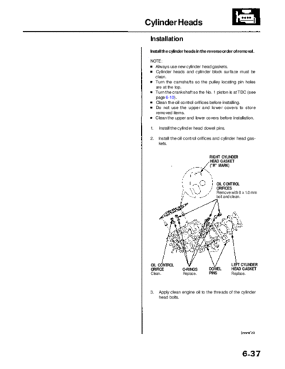
1. Install the cylinder head dowel pins.
2. Install the oil control orifices and cylinder head gas-
kets.
RIGHT CYLINDER
HEAD GASKET
("R" MARK)
OIL CONTROL
ORIFICES
Remove with 6 x 1.0 mm
bolt and clean.
OIL CONTROL LEFT CYLINDER
ORIFICE O-RINGS DOWEL HEAD GASKET
Clean. Replace. PINS Replace.
3. Apply clean engine oil to the threads of the cylinder
head bolts.
Main Menu Table of Contents
Cylinder Heads
Installation (cont'd)
4. Install the cylinder heads on the cylinder block. 6. Install the head cover gasket in the groove of the
cylinder head cover. Seat the recesses for the cam-
5. Tighten the cylinder head bolts sequentially in 2 or shaft first, then work it into the groove around the
3 steps. outside edges.
Specified Torque: NOTE:
76 N-m (7.8 kgf-m, 56 Ibf-ft) Before installing the cylinder head cover gasket,
thoroughly clean the seal and the groove.
NOTE: When installing, make sure the head cover gasket
We recommend using a beam-type torque wrench. is seated securely in the corners of the recesses
When using a preset-type torque wrench, be sure with no gap.
to tighten slowly and not to overtighten.
If a bolt makes any noise while you are torquing
it, loosen the bolt and retighten it. HEAD COVER
CORNERS OF GASKET CORNERS OF
THE RECESS Clean. THE RECESS
CYLINDER HEAD BOLTS TORQUE SEQUENCE
CYLINDER
HEAD COVER
7. Apply liquid gasket to the head cover gasket at the
four corners of the recesses.
CYLINDER HEAD BOLTS
Apply engine oil to the bolt NOTE:
threads. Use liquid gasket, Part No. 08718 - 0001 or 08718
- 0003.
Check that the mating surfaces are clean and dry
before applying liquid gasket.
Do not install the parts if five minutes or more have
elapsed since applying liquid gasket. Instead, reap-
ply liquid gasket after removing old residue.
After assembly, wait at least 30 minutes before
filling the engine with oil.
Apply liquid gasket to
the shaded areas.
Main Menu Table of Contents
8. When installing the cylinder head cover, hold the 10. Install the left and right back covers, then install the
head cover gasket in the groove by placing your fin- left and right camshaft pulleys.
gers on the camshaft holder contacting surfaces
(top of the semicircles).
Once the cylinder head cover is on the cylinder head, LEFT
CAMSHAFT PULLEY
slide the cover slightly back and forth to seat the
head cover gasket.
NOTE:
Before installing the cylinder head cover, clean
the cylinder head contacting surfaces with a
shop towel.
Do not touch the parts where liquid gasket was
applied.
Replace the washer when damaged or deterio-
rated.
BACK COVER
WASHER
CYLINDER
HEAD COVER
8 x 1.25 mm
31 N-m (3.2 kgf-m,
23 Ibf-ft)
6 x 1.0 mm
12 N-m (1.2 kgf-m,
8.7 Ibf-ft)
RIGHT
CAMSHAFT PULLEY
9. Tighten the nuts in 2 or 3 steps. In the final step, tight-
en all nuts, in sequence, to 12 N-m (1.2 kgf-m,
8.7 Ibf-ft).
NOTE: After assembly, wait at least 30 minutes
before filling the engine with oil.
8 x 1.25 mm BACK COVER
31 N-m (3.2 kgf-m,
23 Ibf-ft)
6 x 1.0 mm
12 N-m (1.2 kgf-m,
8.7 Ibf-ft)
11. Install the timing belt and balancer belt (see page 6-10).
Main Menu Table of Contents
Cylinder Heads
Installation (cont'd)
12. Install the intake manifold and water passage, then
tighten the intake manifold mounting bolts and nuts
in a crisscross pattern in 2 or 3 steps, beginning
with the inner bolts.
NOTE: Always use new intake manifold gaskets.
13. Install the EGR pipe.
6 x 1.0 mm 8 x 1.25 mm
12 N-m (1.2 kgf-m, 22 N-m (2.2 kgf-m, 16 Ibf-ft)
8.7 Ibf-ft)
GASKETS
Replace.
6 x 1.0 mm
12 N-m (1.2 kgf-m,
8.7 Ibf-ft)
WATER
PASSAGE
EGR PIPE
GASKETS
Replace.
O-RING
Replace.
14. Install the exhaust manifolds. Tighten the nuts in a
crisscross pattern in 2 or 3 steps, beginning with the
inner nut (see page 9-4).
NOTE: Always use new exhaust manifold gaskets.
15. After installation, check that all tubes, hoses and
connectors are installed correctly.
16. Enter the anti-theft code for the radio, then enter the
customer's radio station presets.
◦ Jabse Service Manual Search 2026 ◦ Jabse Pravopis ◦ onTap.bg ◦ Other service manual resources online : Fixya ◦ eServiceinfo