Service Manuals, User Guides, Schematic Diagrams or docs for : . Car Manuals Acura 3.5RL 1996-2004 Approved srm RL9604S07010A
<< Back | HomeMost service manuals and schematics are PDF files, so You will need Adobre Acrobat Reader to view : Acrobat Download Some of the files are DjVu format. Readers and resources available here : DjVu Resources
For the compressed files, most common are zip and rar. Please, extract files with Your favorite compression software ( WinZip, WinRAR ... ) before viewing. If a document has multiple parts, You should download all, before extracting.
Good luck. Repair on Your own risk. Make sure You know what You are doing.
Image preview - the first page of the document

>> Download RL9604S07010A documenatation <<
Text preview - extract from the document
               Main Menu                Table of Contents


Pistons and Crankshaft
 Removal
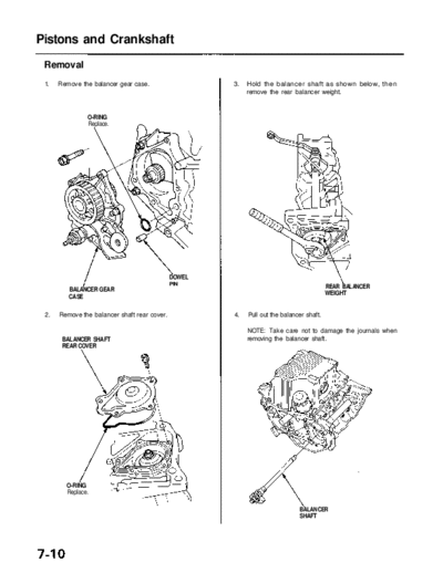
 1.   Remove the balancer gear case.                        3.   Hold the balancer shaft as shown below, then
                                                                 remove the rear balancer weight.


               O-RING
               Replace.


                                              DOWEL
                                              PIN
                                                                                                REAR BALANCER
         BALANCER GEAR                                                                          WEIGHT
         CASE

 2.   Remove the balancer shaft rear cover.                 4.   Pull out the balancer shaft.

                                                                 NOTE: Take care not to damage the journals when
       BALANCER SHAFT                                            removing the balancer shaft.
       REAR COVER


        O-RING
        Replace.

                                                                                    BALANCER
                                                                                    SHAFT
              Main Menu                  Table of Contents


5.    Remove the balancer shaft holder (see page 7-3).       9. If you can feel a ridge of metal or hard carbon around
                                                                the top of any cylinder, remove it with a ridge reamer.
6.    Remove the oil pan assembly.                              Follow the reamer manufacturer's instructions.

7.    Remove the rear cover.                                     CAUTION: If the ridge is not removed, it may damage
                                                                 the pistons as they are pushed out.

      DOWEL
      PIN


                                                                                                      RIDGE REAMER
                                                                                                      (Commercially
                                                                                                      available)

                              O-RING
                              Replace.                       10. Remove the connecting rod caps after setting the
     REAR COVER                                                  crank pin at BDC for each cylinder. Remove the pis-
                                                                 ton assembly by pushing on the connecting rod.

                                                                 CAUTION: Take care not to damage the crank pin or
                                                                 cylinder with the connecting rod.
8.    Remove the oil pump.                                                                CORRECT

                  O-RINGS
                  Replace.


                                                                               PISTON
                                                                                                           INCORRECT


                                         DOWEL
                                         PIN


                   OIL PUMP

                                                                                                 PISTON
                Main Menu                   Table of Contents


Pistonsand Crankshaft
 Removal (cont'd)
 11. Remove the bearing from the cap. Keep all caps/bear-         To help with removal of the caps, install the cap bolts in
     ings in order.                                               the outside bolt holes.

 12. Remove the upper bearing halves from the connecting
     rods, and set them aside with their respective caps.

 13. After removing each piston/connecting rod assem-                 CAP BOLT
     bly, reinstall the cap on the rod.

 14. To avoid mixup during reassembly, mark each pis-
     ton/connecting rod assembly with its cylinder num-
     ber.

     NOTE: The existing number on the connecting rod
     does not indicate its position in the engine, it indicates
     the rod bore size.

 15. Remove the bearing cap bolts and bearing cap side
     bolts, then remove the bearing cap.
                                                                                     MAIN BEARING CAPS

                                          MAIN BEARING
                                          CAP


     RUBBER
     CAP                                                          16. Lift the crankshaft out of the cylinder block, being
                                                                      careful not to damage the journals.


                                                                                                     CRANKSHAFT


                                                                  17. Reinstall the main caps and bearings on the cylin-
                                                                      der block in proper order.
◦ Jabse Service Manual Search 2024 ◦ Jabse Pravopis ◦ onTap.bg ◦ Other service manual resources online : Fixya ◦ eServiceinfo