Service Manuals, User Guides, Schematic Diagrams or docs for : . Car Manuals Acura 3.5RL 1996-2004 Approved srm RL9604S11118A
<< Back | HomeMost service manuals and schematics are PDF files, so You will need Adobre Acrobat Reader to view : Acrobat Download Some of the files are DjVu format. Readers and resources available here : DjVu Resources
For the compressed files, most common are zip and rar. Please, extract files with Your favorite compression software ( WinZip, WinRAR ... ) before viewing. If a document has multiple parts, You should download all, before extracting.
Good luck. Repair on Your own risk. Make sure You know what You are doing.
Image preview - the first page of the document

>> Download RL9604S11118A documenatation <<
Text preview - extract from the document
            Main Menu                      Table of Contents


Idle Control System
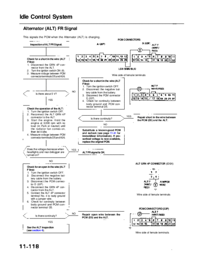
 Alternator (ALT) FR Signal
 This signals the PCM when the Alternator (ALT) is charging.
                                                                                      PCM CONNECTORS
      Inspection of ALT FR Signal.


    Check for a short in the wire (ALT
    F line):
    1. Disconnect the GRN 4P con-
         nector from the ALT.
    2. Turn the ignition switch ON (II).
    3. Measure voltage between PCM
                                                                                  Wire side of female terminals
        connector terminals D5 and A26.
                                                      Check for a short in the wire (ALT
                                                      F line):
                                                      1. Turn the ignition switch OFF.
                                                      2. Disconnect the negative bat-
                                             NO           tery cable from the battery.
            Is there about 5 V?
                                                      3. Disconnect the PCM connector
                                                           D (22P).
                       YES                            4. Check for continuity between
                                                           body ground and PCM con-
                                                           nector terminal D5.
    Check the operation of the ALT:
    1. Turn the ignition switch OFF.
    2. Reconnect the ALT GRN 4P
       connector to the ALT.                                                                  YES       Repair short in the wire between
                                                               Is there continuity?
    3. Start the engine. Hold the                                                                       the PCM (D5) and the ALT.
       engine at 3,000 rpm with no
                                                                          NO
       load (in Park or neutral) until
       the radiator fan comes on,
                                                      Substitute a known-good PCM
       then let it idle.
                                                      and recheck (see page 11-41 for
    4. Measure voltage between PCM
                                                      immobilizer information). If pre-
       connector terminals D5 and A26.
                                                      scribed voltage is now available,
                                                      replace the original PCM.

   Does the voltage decrease when           YES
   headlights and rear defogger are                  ALT FR signal is OK.
   turned on?

                        NO
                                                                                                      ALT GRN 4P CONNECTOR (C131)
   Check for an open in the wire (ALT
   F line):
   1. Turn the ignition switch OFF.
   2. Disconnect the negative bat-
       tery cable from the battery.
   3. Disconnect the PCM connec-
       tor D (22P).
   4. Disconnect the GRN 4P con-
       nector from the ALT.
   5. Connect the ALT 4P connector
                                                                                                       Wire side of female terminals
       terminal No. 4 to body ground
       with a jumper wire.
   6. Check for continuity between
       body ground and PCM con-
       nector terminal D5.
                                                                                                         PCM CONNECTOR D (22P)
                                             NO      Repair open wire between the
           Is there continuity?
                                                     PCM (D5) and the ALT.
                       YES

   See the ALT inspection
   (see section 4).
                                                                                                      Wire side of female terminals
◦ Jabse Service Manual Search 2024 ◦ Jabse Pravopis ◦ onTap.bg ◦ Other service manual resources online : Fixya ◦ eServiceinfo