Service Manuals, User Guides, Schematic Diagrams or docs for : . Car Manuals Acura 3.5RL 1996-2004 Approved srm RL9604S11143A
<< Back | HomeMost service manuals and schematics are PDF files, so You will need Adobre Acrobat Reader to view : Acrobat Download Some of the files are DjVu format. Readers and resources available here : DjVu Resources
For the compressed files, most common are zip and rar. Please, extract files with Your favorite compression software ( WinZip, WinRAR ... ) before viewing. If a document has multiple parts, You should download all, before extracting.
Good luck. Repair on Your own risk. Make sure You know what You are doing.
Image preview - the first page of the document
>> Download RL9604S11143A documenatation <<
Text preview - extract from the document
Main Menu   Table of Contents


                                Fuel Gauge
                                Testing

                                NOTE: Refer to section 23 for the fuel gauge system cir-
                                cuit.

                                1.   Check the No. 13 METER (7.5 A) fuse in the under-
                                     dash fuse/relay box, METER (15 A) fuse in the under-
                                     hood fuse/relay box and gauge relay before testing.

                                2.   Remove the rear seat cushion (see section 20).

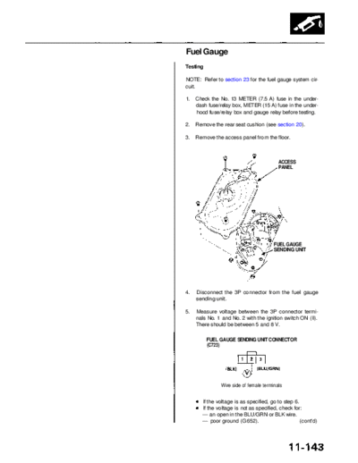
                                3.   Remove the access panel from the floor.


                                                                           ACCESS
                                                                           PANEL


                                                                         FUEL GAUGE
                                                                         SENDING UNIT


                                4.   Disconnect the 3P connector from the fuel gauge
                                     sending unit.

                                5.   Measure voltage between the 3P connector termi-
                                     nals No. 1 and No. 2 with the ignition switch ON (II).
                                     There should be between 5 and 8 V.

                                          FUEL GAUGE SENDING UNIT CONNECTOR
                                          (C723)


                                                Wire side of female terminals


                                        If the voltage is as specified, go to step 6.
                                        If the voltage is not as specified, check for:
                                        -- an open in the BLU/GRN or BLK wire.
                                        -- poor ground (G652).                        (cont'd)
             Main Menu                Table of Contents


Fuel Supply System
 Fuel Gauge (cont'd)
 6.   Turn the ignition switch OFF.

 7.   Attach a jumper wire between the No. 1 and No. 2
      terminals, then turn the ignition switch ON (II).

 8.   Check that the pointer of the fuel gauge starts mov-
      ing toward the "F" mark.

      CAUTION: Turn the ignition switch OFF before the
      pointer reaches "F" on the gauge dial. Failure to do
      so may damage the fuel gauge.

      NOTE: The fuel gauge is a bobbin (cross-coil) type,
      hence the fuel level is continuously indicated even
      when the ignition switch is OFF, and the pointer
      moves more slowly than that of a bimetal type.
◦ Jabse Service Manual Search 2026 ◦ Jabse Pravopis ◦ onTap.bg ◦ Other service manual resources online : Fixya ◦ eServiceinfo