Service Manuals, User Guides, Schematic Diagrams or docs for : . Car Manuals Acura 3.5RL 1996-2004 Approved srm RL9604S11147A
<< Back | HomeMost service manuals and schematics are PDF files, so You will need Adobre Acrobat Reader to view : Acrobat Download Some of the files are DjVu format. Readers and resources available here : DjVu Resources
For the compressed files, most common are zip and rar. Please, extract files with Your favorite compression software ( WinZip, WinRAR ... ) before viewing. If a document has multiple parts, You should download all, before extracting.
Good luck. Repair on Your own risk. Make sure You know what You are doing.
Image preview - the first page of the document
>> Download RL9604S11147A documenatation <<
Text preview - extract from the document
              Main Menu                  Table of Contents


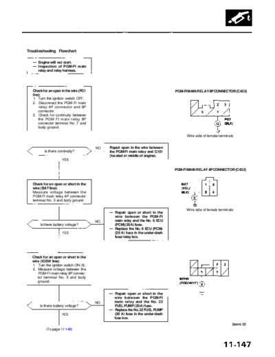
Troubleshooting Flowchart

     Engine will not start.
     Inspection of PGM-FI main
     relay and relay harness.


  Check for an open in the wire (PG1                                               PGM-FI MAIN RELAY 8P CONNECTOR (C433)
  line):
  1. Turn the ignition switch OFF.
  2. Disconnect the PGM-FI main
      relay 4P connector and 8P
      connector.
  3. Check for continuity between
      the PGM-FI main relay 8P
      connector terminal No. 7 and
      body ground.

                                                                                         Wire side of female terminals


                                         NO     Repair open in the wire between
          Is there continuity?                  the PGM-FI main relay and G101
                                                (located at middle of engine).
                     YES

                                                                                   PGM-FI MAIN RELAY 4P CONNECTOR (C432)


  Check for an open or short in the
  wire (BAT line):
  Measure voltage between the
  PGM-FI main relay 4P connector
  terminal No. 3 and body ground.

                                                                                         Wire side of female terminals
                                                   Repair open or short in the
                                                   wire between the PGM-FI
                                         NO        main relay and the No. 6 ECU
       Is there battery voltage?                   (PCM) (20 A) fuse.
                                                   Replace the No. 6 ECU (PCM)
                     YES                           (20 A) fuse in the under-dash
                                                   fuse/relay box.


  Check for an open or short in the
  wire (IGSW line):
  1. Turn the ignition switch ON (II).
  2. Measure voltage between the
     PGM-FI main relay 8P connec-
     tor terminal No. 5 and body
     ground.


                                                   Repair open or short in the
                                                   wire between the PGM-FI
                                         NO        main relay and the No. 22
       Is there battery voltage?                   FUEL PUMP (20 A) fuse.
                                                   Replace the No. 22 FUEL PUMP
                     YES                           (20 A) fuse in the under-dash
                                                   fuse box.


           (To page 11-148)
             Main Menu                 Table of Contents


Fuel Supply System
 PGM-FI Main Relay (cont'd)
         (From page 11-147)


                                                                                 PGM-FI MAIN RELAY 4P CONNECTOR (C432)
  Check for an open in the wire
  (IGSW line):
  Measure voltage between the
  PGM-FI main relay 4P connector
  terminal No. 4 and body ground.                                                                           IGSW
                                                                                                            (BLK/YEL)


                                                 Repair open or short in the
                                                 wire between the PGM-FI               Wire side of female terminals
                                       NO        main relay and the No. 25 IG
      Is there battery voltage?                  COIL (30 A) fuse.
                                                 Replace the No. 25 IG COIL
                    YES                          (30 A) fuse in the under-dash
                                                 fuse/relay box.


  Check for an open or short in the
  wire (STS line):
  1. Turn the ignition switch to the
     START (III) position (trans-
     mission in    or    position).                                               PGM-FI MAIN RELAY 8P CONNECTOR (C433)
  2. Measure the voltage between
     the PGM-FI main relay 8P con-
     nector terminal No. 3 and
     body ground.


                                                 Repair open or short in the
                                                 wire between the PGM-FI
                                       NO        main relay and the No. 14             Wire side of female terminals
      Is there battery voltage?                  STARTER SIGNAL (7.5 A) fuse.
                                                 Replace the No. 14 STARTER
                    YES                          SIGNAL (7.5 A) fuse in the
                                                 under-dash fuse box.


  Check for an open in the wire
  (FLR1 line):
  1. Turn the ignition switch OFF.
  2. Disconnect the PCM connec-
     tor A (26 P) from the PCM.
  3. Check for continuity between
     the PGM-FI main relay 8P
     connector terminal No. 2 and
     PCM connector terminal A4.


                                                                                               PCM CONNECTOR A (26P)


                                       NO     Repair open in the wire between
         Is there continuity?                 the PCM (A4) and the PGM-FI
                                              main relay.
                    YES                                                                Wire side of female terminals

          (To page 11-149)
             Main Menu                  Table of Contents


       (From page 11-148)


Check for an open in the wires                                                      PCM CONNECTORS
(IGP1, IGP2 lines):
 1. Reconnect the PCM connector
    A (26P).
2. Reconnect the PGM-FI main
    relay 4P and 8P connectors.
3. Turn the ignition switch ON (II).
4. Measure voltage between
    PCM connector terminals
    A13, B1, and A12.


                                                                                  Wire side of female terminals

                                                  Repair open in the wire
                                       NO         between the PCM (A13, B1)
     Is there battery voltage?                    and the PGM-FI main relay.
                                                  Replace the PGM-FI main
                   YES                            relay.


Check for an open in the PCM:
1. Turn the ignition switch OFF.
2. Measure voltage between
   PCM connector terminals A4
   and A12 when the ignition
   switch is first turned on for 2
   seconds.


                                              Substitute a known-good PCM
                                       NO     and recheck (see page 11-42 for
      Is there 1.0V or less?                  immobilizer information). If pre-
                                              scribed voltage is now available,
                   YES                        replace the original PCM.


Check the PGM-FI main relay
(see page 11-146).
◦ Jabse Service Manual Search 2026 ◦ Jabse Pravopis ◦ onTap.bg ◦ Other service manual resources online : Fixya ◦ eServiceinfo