Service Manuals, User Guides, Schematic Diagrams or docs for : . Car Manuals Acura 3.5RL 1996-2004 Approved srm RL9604S14019A
<< Back | HomeMost service manuals and schematics are PDF files, so You will need Adobre Acrobat Reader to view : Acrobat Download Some of the files are DjVu format. Readers and resources available here : DjVu Resources
For the compressed files, most common are zip and rar. Please, extract files with Your favorite compression software ( WinZip, WinRAR ... ) before viewing. If a document has multiple parts, You should download all, before extracting.
Good luck. Repair on Your own risk. Make sure You know what You are doing.
Image preview - the first page of the document
>> Download RL9604S14019A documenatation <<
Text preview - extract from the document
            Main Menu                  Table of Contents


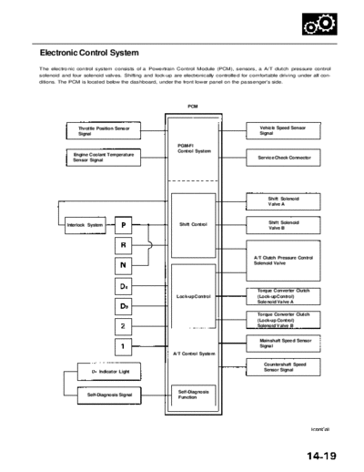
Electronic Control System
The electronic control system consists of a Powertrain Control Module (PCM), sensors, a A/T clutch pressure control
solenoid and four solenoid valves. Shifting and lock-up are electronically controlled for comfortable driving under all con-
ditions. The PCM is located below the dashboard, under the front lower panel on the passenger's side.


                                                                 PCM


                Throttle Position Sensor                                                     Vehicle Speed Sensor
                Signal                                                                       Signal

                                                             PGM-FI
                                                             Control System
              Engine Coolant Temperature
                                                                                             Service Check Connector
              Sensor Signal


                                                                                                 Shift Solenoid
                                                                                                 Valve A


                                                             Shift Control                       Shift Solenoid
           Interlock System
                                                                                                 Valve B


                                                                                           A/T Clutch Pressure Control
                                                                                           Solenoid Valve


                                                                                            Torque Converter Clutch
                                                            Lock-up Control                 (Lock-up Control)
                                                                                            Solenoid Valve A

                                                                                            Torque Converter Clutch
                                                                                            (Lock-up Control)
                                                                                            Solenoid Valve B


                                                                                             Mainshaft Speed Sensor
                                                                                             Signal
                                                           A/T Control System

                                                                                               Countershaft Speed
                         Indicator Light                                                       Sensor Signal


                                                             Self-Diagnosis
                    Self-Diagnosis Signal
                                                             Function
               Main Menu                 Table of Contents

Description

 Electronic Control System (cont'd)
 Shift Control
 The PCM instantly determines which gear should be selected by various signals sent from sensors, and it actuates the
 shift solenoid valves A and B to control shifting. Also, a Grade Logic Control System controls shifting in position while
 the vehicle is ascending or descending a slope, or reducing speed.


 *: See page 14-36 for reverse inhibitor control description.

 Lock-up Control
 From sensor input signals, the PCM determines whether to turn the lock-up ON or OFF and activates torque converter
 clutch (lock-up control) solenoid valve A and/or B accordingly. The combination of driving signals to torque converter
 clutch (lock-up control) solenoid valves A and B is shown in the table below.
              Main Menu                 Table of Contents


Grade Logic Control System

How it works:
The PCM compares actual driving conditions with driving conditions memorized in the PCM, based on the input from the
vehicle speed sensor, throttle position sensor, engine coolant temperature sensor, barometric pressure sensor, brake
pedal position switch signal and shift lever position signal, to control shifting while a vehicle is ascending or descending a
slope.
               Main Menu                Table of Contents

Description

 Electronic Control System (cont'd)
 Ascending Control

 When the PCM determines that the vehicle is climbing a hill in     position, the system extends the engagement area of
 3rd gear to prevent the transmission from frequently shifting between 3rd and 4th gears, so the vehicle can run smooth
 and have more power when needed.

 NOTE:
◦ Jabse Service Manual Search 2026 ◦ Jabse Pravopis ◦ onTap.bg ◦ Other service manual resources online : Fixya ◦ eServiceinfo