Service Manuals, User Guides, Schematic Diagrams or docs for : . Car Manuals Acura 3.5RL 1996-2004 Approved srm RL9604S14052A
<< Back | HomeMost service manuals and schematics are PDF files, so You will need Adobre Acrobat Reader to view : Acrobat Download Some of the files are DjVu format. Readers and resources available here : DjVu Resources
For the compressed files, most common are zip and rar. Please, extract files with Your favorite compression software ( WinZip, WinRAR ... ) before viewing. If a document has multiple parts, You should download all, before extracting.
Good luck. Repair on Your own risk. Make sure You know what You are doing.
Image preview - the first page of the document
>> Download RL9604S14052A documenatation <<
Text preview - extract from the document
               Main Menu                  Table of Contents


Troubleshooting Procedures


 Checking the Diagnostic Trouble Code (DTC)
 with an OBD II Scan Tool or Honda PGM Tester

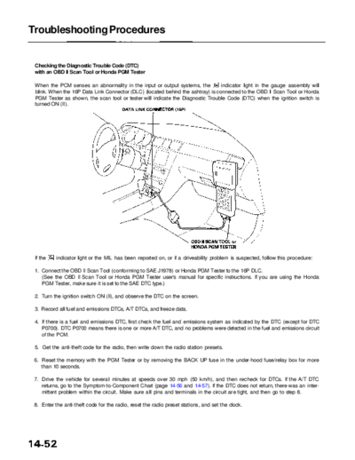
 When the PCM senses an abnormality in the input or output systems, the          indicator light in the gauge assembly will
 blink. When the 16P Data Link Connector (DLC) (located behind the ashtray) is connected to the OBD II Scan Tool or Honda
 PGM Tester as shown, the scan tool or tester will indicate the Diagnostic Trouble Code (DTC) when the ignition switch is
 turned ON (II).


 If the   indicator light or the MIL has been reported on, or if a driveability problem is suspected, follow this procedure:

 1. Connect the OBD II Scan Tool (conforming to SAE J1978) or Honda PGM Tester to the 16P DLC.
    (See the OBD II Scan Tool or Honda PGM Tester user's manual for specific instructions. If you are using the Honda
    PGM Tester, make sure it is set to the SAE DTC type.)

 2. Turn the ignition switch ON (II), and observe the DTC on the screen.

 3. Record all fuel and emissions DTCs, A/T DTCs, and freeze data.

 4. If there is a fuel and emissions DTC, first check the fuel and emissions system as indicated by the DTC (except for DTC
    P0700). DTC P0700 means there is one or more A/T DTC, and no problems were detected in the fuel and emissions circuit
    of the PCM.

 5. Get the anti-theft code for the radio, then write down the radio station presets.

 6. Reset the memory with the PGM Tester or by removing the BACK UP fuse in the under-hood fuse/relay box for more
    than 10 seconds.

 7. Drive the vehicle for several minutes at speeds over 30 mph (50 km/h), and then recheck for DTCs. If the A/T DTC
    returns, go to the Symptom-to-Component Chart (page 14-56 and 14-57). If the DTC does not return, there was an inter-
    mittent problem within the circuit. Make sure all pins and terminals in the circuit are tight, and then go to step 8.

 8. Enter the anti-theft code for the radio, reset the radio preset stations, and set the clock.
            Main Menu                 Table of Contents


Checking the Diagnostic Trouble Code (DTC)
with the Service Check Connector and Special Tool

When the PCM senses an abnormality in the input or output systems, the    indicator light in the gauge assembly will blink.
When the Service Check Connector (located under the dash on the passenger side) is connected with the special tool as
shown, the   indicator light will blink the Diagnostic Trouble Code (DTC) when the ignition switch is turned ON (II).

When the      indicator light has been reported on, connect the Service Check Connector with the special tool.
Then turn the ignition switch ON (II) and observe the    indicator light.
                                                                                         SERVICE CHECK
                                                                                         CONNECTOR (2P)
     GAUGE ASSEMBLY


                                                    INDICATOR
                                                 LIGHT


                                                                     SCS SERVICE CONNECTOR
                                                                     07PAZ-0010100
Codes 1 through 9 are indicated by individual short blinks. Codes 10 and above are indicated by a series of long and short
blinks. One long blink equals 10 short blinks. Add the long and short blinks together to determine the code. After deter-
mining the code, refer to the electrical system Symptom-to-Component Chart on pages 14-56 and 14-57.


NOTE:
◦ Jabse Service Manual Search 2026 ◦ Jabse Pravopis ◦ onTap.bg ◦ Other service manual resources online : Fixya ◦ eServiceinfo