Service Manuals, User Guides, Schematic Diagrams or docs for : . Car Manuals Acura 3.5RL 1996-2004 Approved srm RL9604S14090A
<< Back | HomeMost service manuals and schematics are PDF files, so You will need Adobre Acrobat Reader to view : Acrobat Download Some of the files are DjVu format. Readers and resources available here : DjVu Resources
For the compressed files, most common are zip and rar. Please, extract files with Your favorite compression software ( WinZip, WinRAR ... ) before viewing. If a document has multiple parts, You should download all, before extracting.
Good luck. Repair on Your own risk. Make sure You know what You are doing.
Image preview - the first page of the document
>> Download RL9604S14090A documenatation <<
Text preview - extract from the document
                Main Menu                   Table of Contents


Mainshaft/Countershaft Speed Sensors
 Replacement
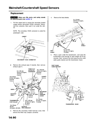
              Make sure lifts, jacks, and safety stands                  4.   Remove the heat shields.
 are placed properly (see section 1).                                                                           6 x 1.0 mm
                                                                                                                9.8 N-m (1.0 kgf-m,
 1.    Pull the carpet back to expose the secondary heated                                                      7.2 Ibf-ft)
       oxygen sensor (secondary HO2S) connector. Discon-
       nect the connector, then push it out under the vehi-
       cle.

       NOTE: The secondary HO2S connector is under the
       passenger's seat.

                         CARPET


                                                                                                                              HEAT
                                                                                                                              SHIELD


                                                                                              6 x 1.0 mm
                                                                         HEAT                 9.8 N-m (1.0 kgf-m,
                                                                         SHIELD               7.2 Ibf-ft)

                                                                         5.    Place a jack under the transmission, and raise the
                                                                              transmission just enough to take weight off of the
                                                                              mounts, then remove the bolt securing the shift
                SECONDARY HO2S CONNECTOR                                      cable guide bracket and the transmission beam.


      Remove the exhaust pipe A bracket, then remove                      SHIFT CABLE
      exhaust pipe A.                                                     GUIDE BRACKET

                                    THREE WAY
                                                    10 x 1.25 mm
                                    CATALYTIC
               8 x 1.25 mm                          33 N-m (3.4 kgf-m,
                                    CONVERTER
               22 N-m (2.2 kgf-m,                   25 Ibf-ft)
               16 Ibf-ft)                           Replace.
               Replace.
10 x 1.25 mm                                                 GASKET
54 N-m (5.5 kgf-m,                                           Replace.
40 Ibf-ft)
Replace.


  BAND                                 GASKET
                                       Replace.
                                                         SECONDARY
                                    8 x 1.25 mm          HO2S
  EXHAUST                           22 N-m (2.2 kgf-m,   HARNESS
  PIPE A                            16 Ibf-ft)           COVER
                                    Replace.
                                                   6 x 1.0 mm
TRANSMISSION                  10 x 1.25 mm         9.8 N-m (1.0 kgf-m,
STOP COLLAR                   33 N-m (3.4 kgf-m,   7.2 Ibf-ft)
                              25 Ibf-ft)
                              Replace.                                                           TRANSMISSION BEAM
10 x 1.25 mm
38 N-m                   EXHAUST
(3.9 kgf-m, 28 Ibf-ft)   PIPE A BRACKET

 3.   Remove the secondary HO2S harness cover, then
      remove the three way catalytic converter.
           Main Menu                   Table of Contents


6. Lower the transmission.                                          10. Raise the transmission with a jack.

7. Remove the 6 mm bolt from the transmission hous-                 11. Install the transmission beam on the rear transmis-
   ing, and remove the mainshaft and countershaft                       sion mount bracket/mount, then tighten the four
   speed sensors.                                                       bolts loosely.
                        6 x 1.0 mm
       MAINSHAFT        12 N-m (1.2 kgf-m, 8.7 Ibf-ft)
       SPEED SENSOR                                                 TRANSMISSION BEAM             6 x 1.0 mm
 WASHER                                                             BOLTS                         9.8 N-m (1.0 kgf-m,
                                                                    10 x 1.25 mm                  7.2 Ibf-ft)
                                                                    38 N-m (3.9 kgf-m,                              SHIFT CABLE
                                                                    28 Ibf-ft)                                      GUIDE BRACKET


                                                         COUNTER-
                                                         SHAFT
                                                         SPEED
                                                         SENSOR

                                                         O-RING
     O-RING                                              Replace.
     Replace.
                       WASHER
8. Replace the O-rings with new ones before reassem-
   bling the mainshaft and countershaft speed sensors.                             TRANSMISSION BEAM BOLTS
                                                                                   10 x 1.25 mm
9. Install washers on the mainshaft and countershaft                               38 N-m (3.9 kgf-m, 28 Ibf-ft)
   speed sensors, then install the sensors on the trans-
   mission housing.
                                                                    12. Tighten the four beam bolts to the specified torque,
                                                                        then tighten the three inner bolts to the specified
                                                                        torque.

                                                                    13. Install the shift cable guide bracket on the transmis-
                                                                        sion beam.

                                                                    14. Install the heat shields.

                                                                    15. Install exhaust pipe A and the three way catalytic
                                                                        converter, then install the exhaust pipe A bracket.

                                                                    16. Push the secondary HO2S connector into the vehi-
                                                                        cle, then secure it with the harness grommet.

                                                                    17. Install the secondary HO2S harness cover.

                                                                    18. Connect the secondary HO2S connector.
◦ Jabse Service Manual Search 2026 ◦ Jabse Pravopis ◦ onTap.bg ◦ Other service manual resources online : Fixya ◦ eServiceinfo