Service Manuals, User Guides, Schematic Diagrams or docs for : . Car Manuals Acura 3.5RL 1996-2004 Approved srm RL9604S14093A
<< Back | HomeMost service manuals and schematics are PDF files, so You will need Adobre Acrobat Reader to view : Acrobat Download Some of the files are DjVu format. Readers and resources available here : DjVu Resources
For the compressed files, most common are zip and rar. Please, extract files with Your favorite compression software ( WinZip, WinRAR ... ) before viewing. If a document has multiple parts, You should download all, before extracting.
Good luck. Repair on Your own risk. Make sure You know what You are doing.
Image preview - the first page of the document
>> Download RL9604S14093A documenatation <<
Text preview - extract from the document
            Main Menu                 Table of Contents


Replacement
             Make sure lifts, jacks and safety stands are placed properly (see section 1).

 1. Raise the front of the vehicle, and support it with safety stands (see section 1).

2. Set the parking brake, and block both rear wheels securely.

3. Shift the transmission to the     position.

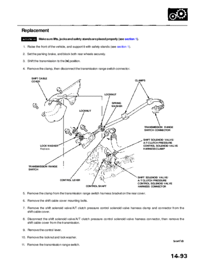
4. Remove the clamp, then disconnect the transmission range switch connector.


       SHIFT CABLE
       COVER                                                                             CLAMPS


                                                                 LOCKNUT


                                                                      SPRING
                                                                      WASHER
                                             LOCKNUT


                                                                                              TRANSMISSION RANGE
                                                                                              SWITCH CONNECTOR


                                                                                             SHIFT SOLENOID VALVE/
                                                                                             A/T CLUTCH PRESSURE
              LOCK WASHER                                                                    CONTROL SOLENOID VALVE
              Replace.                                                                       HARNESS CLAMP


     TRANSMISSION RANGE
     SWITCH


                                                                                          SHIFT SOLENOID VALVE/
                              CONTROL LEVER                                               A/T CLUTCH PRESSURE
                                                                                          CONTROL SOLENOID VALVE
                                                  CONTROL SHAFT                           HARNESS CONNECTOR

 5. Remove the clamp from the transmission range switch harness bracket on the rear cover.

 6. Remove the shift cable cover mounting bolts.

7. Remove the shift solenoid valve/A/T clutch pressure control solenoid valve harness clamp and connector from the
   shift cable cover.

8. Disconnect the shift solenoid valve/A/T clutch pressure control solenoid valve harness connector, then remove the
   shift cable cover from the transmission.

9. Remove the control lever.

10. Remove the locknut and lock washer.

11. Remove the transmission range switch.
            Main Menu                 Table of Contents


Transmission Range Switch (A/T Gear Position Switch)
 Replacement (cont'd)
 12. Set a new transmission range switch to the           posi-   14. Install the transmission range switch on the control
     tion as shown.                                                   shaft, and loosely install the bolts.

     NOTE: The transmission range switch clicks in the                  6 x 1.0 mm BOLTS
                                                                        Loosely install.
       position.


                                        POSITION MARK


                                                                    TRANSMISSION RANGE
                                                                    SWITCH


                                                                                 CONTROL SHAFT
      TRANSMISSION RANGE                                          15. Install a new lock washer on the transmission range
      SWITCH                               CONTROL SHAFT
                                           HOLE                       switch by aligning its projected tip with the   posi-
                                                                      tion mark on the transmission range switch as shown.

                                                                                            TRANSMISSION RANGE
 13. Set the control shaft to the   position.                                               SWITCH
                                                                           LOCK WASHER                       PROJECTED
                                                                                                             TIP
                                                                         LOCK TABS

                                                                       LOCKNUT
                                                                       12 N-m (1.2 kgf-m,
                                                                       8.7 Ibf-ft)


                                                                                                                   POSITION
                                                                                                                 MARK


                                                                  LOCK WASHER
                                                                  Replace.


           CONTROL SHAFT


                                                                      CONTROL
                                                                      SHAFT                 6 x 1.0 mm
                                                                                            12 N-m (1.2 kgf-m,
                                                                                            8.7 Ibf-ft)


                                                                  16. Tighten the locknut while holding the control shaft,
                                                                      then bend the lock tabs against the locknut.

                                                                  17. Tighten the 6 mm bolts to the specified torque.
            Main Menu                         Table of Contents


18. Install the control lever.                                    21. Connect the transmission range switch harness
                                                                      connector, then clamp the harness clamp on the
CAUTION: Take care not to bend the shift cable.                       brackets.

              8 x 1.25 mm                                         22. Turn the ignition switch ON (II). Move the shift lever
              16 N-m (1.6 kgf-m, 12 Ibf-ft)                           through all gears, and check the transmission range
                                                                      switch synchronization with the A/T gear position
                                                                      indicator.


                                                                     GAUGE ASSEMBLY
   SPRING
   WASHER

        CONTROL
        LEVER


           CONTROL SHAFT


19. Connect the shift solenoid valve/A/T clutch pressure
    control solenoid valve harness connector.                                                         A/T GEAR POSITION
                                                                                                      INDICATOR
20. Install the shift solenoid valve/A/T clutch pressure
    control solenoid valve harness clamp to the shift
    cable cover, then install the shift cable cover onto          23. If the transmission range switch is not synchronized
    the transmission.                                                 with the A/T gear position indicator, loosen the bolts
                                                                      securing the transmission range switch and adjust
       6 x 1.0 mm                                                     the transmission range switch installation.
       12 N-m (1.2 kgf-m,
       8.7 Ibf-ft)
                                                                  24. Start the engine. Move the shift lever through all
                                                                      gears, and verify the following:
                                                      CLAMP
◦ Jabse Service Manual Search 2026 ◦ Jabse Pravopis ◦ onTap.bg ◦ Other service manual resources online : Fixya ◦ eServiceinfo