Service Manuals, User Guides, Schematic Diagrams or docs for : . Car Manuals Acura 3.5RL 1996-2004 Approved srm RL9604S14116A

<< Back | Home

Most service manuals and schematics are PDF files, so You will need Adobre Acrobat Reader to view : Acrobat Download Some of the files are DjVu format. Readers and resources available here : DjVu Resources
For the compressed files, most common are zip and rar. Please, extract files with Your favorite compression software ( WinZip, WinRAR ... ) before viewing. If a document has multiple parts, You should download all, before extracting.
Good luck. Repair on Your own risk. Make sure You know what You are doing.


Image preview - the first page of the document
RL9604S14116A


>> Download RL9604S14116A documenatation <<

Text preview - extract from the document
               Main Menu                  Table of Contents


Transmission
 Removal
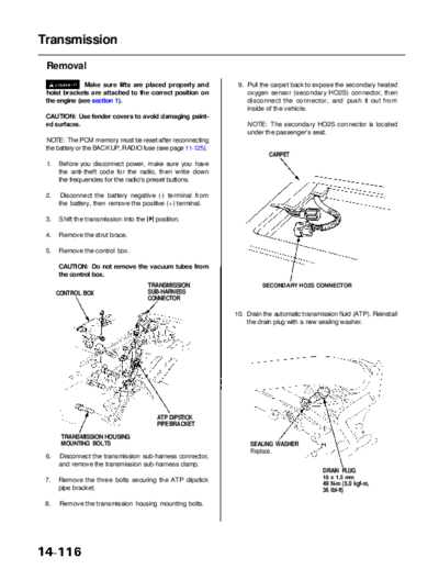
              Make sure lifts are placed properly and          9. Pull the carpet back to expose the secondary heated
 hoist brackets are attached to the correct position on           oxygen sensor (secondary HO2S) connector, then
 the engine (see section 1).                                      disconnect the connector, and push it out from
                                                                  inside of the vehicle.
 CAUTION: Use fender covers to avoid damaging paint-
 ed surfaces.                                                     NOTE: The secondary HO2S connector is located
                                                                  under the passenger's seat.
 NOTE: The PCM memory must be reset after reconnecting
 the battery or the BACK UP, RADIO fuse (see page 11-125).
                                                                          CARPET
 1.   Before you disconnect power, make sure you have
      the anti-theft code for the radio, then write down
      the frequencies for the radio's preset buttons.

 2.    Disconnect the battery negative (-) terminal from
      the battery, then remove the positive (+) terminal.

 3.    Shift the transmission into the     position.

 4.   Remove the strut brace.

 5.   Remove the control box.

      CAUTION: Do not remove the vacuum tubes from
      the control box.
                                         TRANSMISSION                   SECONDARY HO2S CONNECTOR
      CONTROL BOX                        SUB-HARNESS
                                         CONNECTOR

                                                              10. Drain the automatic transmission fluid (ATP). Reinstall
                                                                  the drain plug with a new sealing washer.


                                           ATP DIPSTICK
                                           PIPE BRACKET

       TRANSMISSION HOUSING
       MOUNTING BOLTS                                              SEALING WASHER
                                                                   Replace.
 6.   Disconnect the transmission sub-harness connector,
      and remove the transmission sub-harness clamp.
                                                                                              DRAIN PLUG
                                                                                              18 x 1.5 mm
 7.   Remove the three bolts securing the ATP dipstick
                                                                                             49 N-m (5.0 kgf-m,
      pipe bracket.                                                                          36 Ibf-ft)

 8.    Remove the transmission housing mounting bolts.
            Main Menu                     Table of Contents


11. Remove the transmission stop collars, then remove              14. Remove the ATP cooler hoses at the ATP cooler
    the exhaust pipe A.                                                lines. Turn the ends of the cooler hoses up to pre-
                                                                       vent ATP from flowing out, then plug the ATP cooler
                                                        GASKET         lines and hoses.
   THREE WAY CATALYTIC                                  Replace.
   CONVERTER                                                           NOTE: Check for any signs of leakage from the
                                                                       hoses and the lines.


                                                                                                   SHIFT CABLE
                                                                                                   HOLDER
                                                                                                                 WASHER

                                                                                   CONTROL
                                                                                   LEVER        SHIFT
                                                                   SHIFT CABLE                  CABLE
                                                                   COVER


                               GASKET
                               Replace.           SECONDARY
                                                  HO2S
                                                  HARNESS
 TRANSMISSION       EXHAUST                       COVER
 STOP COLLAR        PIPE A
                                                                   ATF DIPSTICK
                                                                   TUBE                                       SHIFT CABLE
                                                                                                              HOLDER BASE
                                                                      O-RING
                                                                      Replace.

                                                                     ATF COOLER
12. Remove the secondary HO2S harness cover, then                    LINES                      SHIFT SOLENOID VALVE/
    remove the three way catalytic converter.                                                   A/T CLUTCH PRESSURE
                                                                                                CONTROL SOLENOID VALVE
                                                                                  ATF COOLER    HARNESS CONNECTOR
13. Remove the heat shields.                                                      HOSES


                                                                   15. Remove the shift cable cover mounting bolts, then
                                                                       remove the shift solenoid valve/A/T clutch pressure
                                                                       control solenoid valve harness connector and clamp
                                                                       from the shift cable cover.

                                                                   16. Remove the shift cable cover from the transmission
                                                                       housing.
                                               Loosen these
                                               bolts.
                                                                   17. Remove the shift cable holder with shift cable from
                        HEAT SHIELD                                    the shift cable holder base.

                                                                   18. Remove the control lever from the control shaft.
 HEAT SHIELD
                                                                   19. Remove the ATF dipstick tube from the torque con-
                                                                       verter housing.
             Main Menu                  Table of Contents


Transmission
 Removal (cont'd)
 20. Disconnect the transmission range switch connector,    22. Remove the shift cable guide bracket from the
     then remove the clamp from the harness bracket.            transmission beam.

                                                                CAUTION: Take care not to bend the shift cable.
                 CLAMP
                                                              SHIFT CABLE
                                                              GUIDE

                                                                                                      TRANSMISSION
                                                                                                      REAR MOUNT
                                                                                                      BRACKET/MOUNT


                                                                                                     EXHAUST PIPE
                                                                                                     BRACKET
                                                 HARNESS
                                                 BRACKET


                                    TRANSMISSION RANGE      TRANSMISSION
                                    SWITCH CONNECTOR        BEAM

                                                            23. Place a jack under the transmission, and raise the
                                                                transmission just enough to take weight off of the
 21. Remove the lower plate, and reinstall the steering         mounts, then remove the transmission beam, rear
     gearbox mounting bolts as shown.                           transmission bracket/mount and exhaust pipe bracket.

                                                            24. Make sure the transmission is in    position, then
                                   STEERING GEARBOX             remove the 36 mm sealing bolt and O-ring ('00
                                                                model) from the secondary driven gear shaft.

                                                                NOTE: If the transmission is in any position other than
                                                                  shift into    position by rotating the control shaft.

                                                                                                36 mm SEALING BOLT


                                                                                                            O-RING
                                                                                                            Replace.
                                                                                                            '00 model


                                                             EXTENSION SHAFT
                                                             PULLER
                                                             07LAC-PW50101


                                               LOWER
        STEERING GEARBOX                       PLATE
        MOUNTING BOLTS
        Reinstall these bolts on
        the steering gearbox.


                                                            25. Remove the extension shaft from the differential
                                                                using the special tool as shown.
            Main Menu                Table of Contents


26. Remove the transmission housing mounting bolts.         31. Pull the transmission away from the engine until it
                                                                clears the dowel pins, then lower it on the transmis-
                                                                sion jack.


                                   TRANSMISSION HOUSING
                                   MOUNTING BOLT


   TRANSMISSION
   HOUSING MOUNTING
   BOLTS


27. Remove the engine stiffener.


     TRANSMISSION HOUSING
                                       DRIVE PLATE
     MOUNTING BOLT
                                       BOLT


                                                ENGINE
                                                STIFFENER


        26 mm SHIM
                               TORQUE CONVERTER
                               COVERS


28. Remove the torque converter covers.

29. Remove the six drive plate bolts one at a time while
    rotating the crankshaft pulley.

    NOTE: If necessary, remove the spark plugs while
    removing the drive plate bolts.

30. Remove the transmission housing mounting bolts.


◦ Jabse Service Manual Search 2026 ◦ Jabse PravopisonTap.bg ◦ Other service manual resources online : FixyaeServiceinfo