Service Manuals, User Guides, Schematic Diagrams or docs for : . Car Manuals Acura 3.5RL 1996-2004 Approved srm RL9604S14164A
<< Back | HomeMost service manuals and schematics are PDF files, so You will need Adobre Acrobat Reader to view : Acrobat Download Some of the files are DjVu format. Readers and resources available here : DjVu Resources
For the compressed files, most common are zip and rar. Please, extract files with Your favorite compression software ( WinZip, WinRAR ... ) before viewing. If a document has multiple parts, You should download all, before extracting.
Good luck. Repair on Your own risk. Make sure You know what You are doing.
Image preview - the first page of the document
>> Download RL9604S14164A documenatation <<
Text preview - extract from the document
                 Main Menu                  Table of Contents


Clutch

 Disassembly
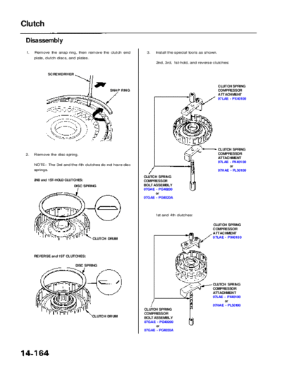
 1.   Remove the snap ring, then remove the clutch end           3.   Install the special tools as shown.
      plate, clutch discs, and plates.
                                                                      2nd, 3rd, 1st-hold, and reverse clutches:


              SCREWDRIVER


                                                                                                            CLUTCH SPRING
                                                  SNAP RING                                                 COMPRESSOR
                                                                                                            ATTACHMENT
                                                                                                            07LAE - PX40100


                                                                                                            CLUTCH SPRING
 2.   Remove the disc spring.                                                                               COMPRESSOR
                                                                                                            ATTACHMENT
                                                                                                            07LAE - PX40100
      NOTE: The 3rd and the 4th clutches do not have disc                                                         or
      springs.                                                                                              07HAE - PL50100
                                                                CLUTCH SPRING
      2ND and 1ST-HOLD CLUTCHES:                                COMPRESSOR
                             DISC SPRING                        BOLT ASSEMBLY
                                                                07GAE - PG40200
                                                                      or
                                                                07GAE - PG4020A


                                                                      1st and 4th clutches:

                                                                                                      CLUTCH SPRING
                                                                                                      COMPRESSOR
                                                                                                      ATTACHMENT
                                         CLUTCH DRUM                                                  07LAE - PX40100


      REVERSE and 1ST CLUTCHES:

                              DISC SPRING


                                                                                                      CLUTCH SPRING
                                                                                                      COMPRESSOR
                                                                                                      ATTACHMENT
                                                                                                      07LAE - PX40100
                                                                                                            or
                                                                                                      07HAE - PL50100
                                                                CLUTCH SPRING
                                                                COMPRESSOR
                                         CLUTCH DRUM            BOLT ASSEMBLY
                                                                07GAE - PG40200
                                                                      or
                                                                07GAE - PG4020A
                 Main Menu                 Table of Contents


CAUTION: If either end of the special tool is set over an           Remove the snap ring. Then remove the special tools,
area of the spring retainer which is unsupported by the             spring retainer and return spring.
return spring, the retainer may be damaged. Be sure the
special tool is adjusted to have full contact with the
spring retainer.
                                         SPECIAL TOOL                  SPECIAL TOOL


                                                                          SNAP RING
                                                                                                   RETURN SPRING
     Set here.                                                                        SPRING RETAINER
                                Do not set here.


                                                               6.   Wrap a shop rag around the clutch drum, and apply
                                            SPECIAL TOOL            air pressure to the oil passage to remove the piston.
                                                                    Place a finger tip on the other end while applying
                                                                    air pressure.

                                                                                                 OSHA - APPROVED
                                                                                                 30 psi NOZZLE


                                        SPRING RETAINER


4.   Compress the return spring with the special tool.


                                                                        CLUTCH
                                                                        DRUM


                                                                       PISTON
◦ Jabse Service Manual Search 2026 ◦ Jabse Pravopis ◦ onTap.bg ◦ Other service manual resources online : Fixya ◦ eServiceinfo