Service Manuals, User Guides, Schematic Diagrams or docs for : . Car Manuals Acura 3.5RL 1996-2004 Approved srm RL9604S14189A

<< Back | Home

Most service manuals and schematics are PDF files, so You will need Adobre Acrobat Reader to view : Acrobat Download Some of the files are DjVu format. Readers and resources available here : DjVu Resources
For the compressed files, most common are zip and rar. Please, extract files with Your favorite compression software ( WinZip, WinRAR ... ) before viewing. If a document has multiple parts, You should download all, before extracting.
Good luck. Repair on Your own risk. Make sure You know what You are doing.


Image preview - the first page of the document
RL9604S14189A


>> Download RL9604S14189A documenatation <<

Text preview - extract from the document
               Main Menu                Table of Contents

Transmission
 Installation
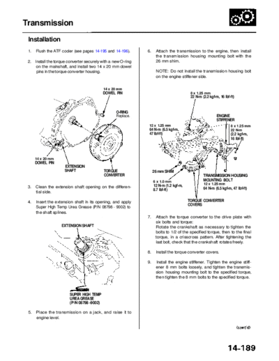
 1.   Flush the ATF cooler (see pages 14-195 and 14-196).     6.    Attach the transmission to the engine, then install
                                                                    the transmission housing mounting bolt with the
 2. Install the torque converter securely with a new O-ring         26 mm shim.
     on the mainshaft, and install two 14 x 20 mm dowel
     pins in the torque converter housing.                          NOTE: Do not install the transmission housing bolt
                                                                    on the engine stiffener side.


                                            14 x 20 mm
                                            DOWEL PIN                                    8 x 1.25 mm
                                                                                         22 N-m (2.2 kgf-m, 16 Ibf-ft)


                                                  O-RING
                                                  Replace.                                                ENGINE
                                                                                                          STIFFENER
                                                               12 x 1.25 mm                                        8 x 1.25 mm
                                                               64 N-m (6.5 kgf-m,                                  22 N-m
                                                               47 Ibf-ft)                                          (2.2 kgf-m,
                                                                                                                   16 Ibf-ft)


      14 x 20 mm
      DOWEL PIN
                     EXTENSION
                     SHAFT                  TORQUE                 26 mm SHIM
                                            CONVERTER                                            TRANSMISSION HOUSING
                                                                   6 x 1.0 mm                    MOUNTING BOLT
                                                                   12 N-m (1.2 kgf-m,            12 x 1.25 mm
 3.   Clean the extension shaft opening on the differen-                                         64 N-m (6.5 kgf-m, 47 Ibf-ft)
                                                                   8.7 Ibf-ft)
      tial side.

 4.   Insert the extension shaft in its opening, and apply                              TORQUE CONVERTER
                                                                                        COVERS
      Super High Temp Urea Grease (P/N 08798 - 9002) to
      the shaft splines.
                                                              7.    Attach the torque converter to the drive plate with
                                                                    six bolts and torque:
                    EXTENSION SHAFT                                 Rotate the crankshaft as necessary to tighten the
                                                                    bolts to 1/2 of the specified torque, then to the final
                                                                    torque, in a crisscross pattern. After tightening the
                                                                    last bolt, check that the crankshaft rotates freely.

                                                              8.    Install the torque converter covers.

                                                              9.    Install the engine stiffener. Tighten the engine stiff-
                                                                    ener 8 mm bolts loosely, and tighten the transmis-
                                                                    sion housing mounting bolt to the specified torque,
                                                                    then tighten the 8 mm bolts to the specified torque.


                        SUPER HIGH TEMP
                        UREA GREASE
                        (P/N 08798 -9002)

 5.   Place the transmission on a jack, and raise it to
      engine level.
            Main Menu                   Table of Contents

Transmission
 Installation (cont'd)
 10. Install the transmission housing mounting bolts          12. Tighten the transmission beam outer bolts (four
     from the transmission side.                                  bolts).
                                                                                    TRANSMISSION BEAM
                                                                                    CENTER BOLTS
                                                                                    10 x 1.25 mm
                                                                                    38 N-m (3.9 kgf-m, 28 Ibf-ft)
        TRANSMISSION HOUSING
        MOUNTING BOLTS
        12 x 1.25 mm
        64 N-m (6.5 kgf-m, 47 Ibf-ft)


                                                             TRANSMISSION
                                                             BEAM OUTER BOLT                          TRANSMISSION
                                                             10 x 1.25 mm                             BEAM OUTER BOLTS
                                                             38 N-m       REAR TRANSMISSION           10 x 1.25 mm
                                                             (3.9 kgf-m,  MOUNT BRACKET BOLTS         38 N-m (3.9 kgf-m,
                                                             28 Ibf-ft)   10 x 1.25 mm                28 Ibf-ft)
                                                                          38 N-m
 11. Install the transmission beam to the rear transmis-                  (3.9 kgf-m, 28 Ibf-ft)
     sion mount bracket/mount. Tighten the three center       13. Tighten the rear transmission mount bracket bolts
     bolts loosely, then install them with the exhaust            (three bolts).
     pipe bracket on the rear cover and body.
                                                              14. Tighten the transmission beam center bolts (three
                                                                  bolts) installed loosely in step 11.
                         REAR TRANSMISSION MOUNT
       REAR TRANSMISSION BRACKET BOLTS
       MOUNT BRACKET/    10 x 1.25 mm                         15. Remove the transmission jack from the transmis-
       MOUNT             38 N-m (3.9 kgf-m, 28 Ibf-ft)            sion.

                                                              16. Install the shift cable guide bracket on the transmis-
                                                                  sion beam.
                                                                                 SHIFT CABLE GUIDE
                                                                                                        6 x 1.0 mm
                                                                                  BRACKET
                                                                                                        9.8 N-m (1.0 kgf-m,
                                                                                                        7.2 Ibf-ft)
                                                                       SHIFT CABLE

                                              EXHAUST PIPE
                                              BRACKET
                                              TRANSMISSION
                                              BEAM


    SHIFT CABLE
    GUIDE BRACKET


                     TRANSMISSION           TRANSMISSION
                     BEAM CENTER BOLTS      BEAM BOLTS
                     10 x 1.25 mm           10 x 1.25 mm
                     Loosely install.

                                                                     TRANSMISSION BEAM
              Main Menu                 Table of Contents


17. Connect the transmission range switch connector,        19. Install the extension shaft using the special tool as
    then install the clamp to the harness bracket.              shown.

                                                                NOTE: Push the extension shaft in the secondary
                CLAMP                                           driven gear shaft until the extension shaft stops.


                                                              EXTENSION SHAFT
                                              HARNESS         INSTALLER
                                              BRACKET         07MAF-PY40101


                                                                                                        SET RING


                              TRANSMISSION RANGE
                              SWITCH CONNECTOR


18. Install a new set ring in the extension shaft groove.
                                                                                                        EXTENSION
                                                                                                        SHAFT

               SET RING                                     20. Remove the special tool.

                                                            21. Fill the opening between the secondary driven gear
                                                                shaft and the extension shaft with High Temp Urea
                                                                Grease (P/N 08798 - 9002), as shown.


                                                                            SUPER HIGH TEMP UREA GREASE
                                                                            (P/N 08798-9002)
                                                                            12-14 g (0.4-0.5 oz)


               EXTENSION SHAFT
               Main Menu                       Table of Contents

Transmission
 Installation (cont'd)
 22. Shift the transmission to the           position by rotating   24. Remove the steering gearbox mounting bolts, then
     the control shaft.                                                 install the lower plate.

 23. Install the 36 mm sealing bolt.
     '96 - '99 models:                                                                              STEERING GEARBOX
     Apply liquid gasket (P/N 08718 - 0001) to the 36 mm
     sealing bolt threads, then install and tighten the
     sealing bolt.


       SEALING BOLT. 36 mm
       78 N-m (8.0 kgf-m, 58 Ibf-ft)
                                        Apply liquid gasket
                                        to the threads.


                                                                       STEERING GEARBOX
                                                                       MOUNTING BOLTS          10 x 1.25 mm             LOWER
                                                                       10 x 1.25 mm            38 N-m                   PLATE
                                                                       59 N-m (6.0 kgf-m,      (3.9 kgf-m, 28 Ibf-ft)
                                                                       43 Ibf-ft)


                                                                    25. Install the control lever on the control shaft.

                                                                         CAUTION: Take care not to bend the shift cable.

     '00-01 models:
     Clean the opening bore of the secondary gear shaft.                                                       6 x 1.0 mm
                                                                                                               12 N-m (1.2 kgf-m,
     Install the new O-ring on the sealing bolt, then                                  LOCKNUT                 8.7 Ibf-ft)
     install them, and tighten the sealing bolt.                                       16 N-m (1.6 kgf-m,
                                                                                       12 Ibf-ft)
                                                                    6 x 1.0 mm                         SPRING
                                                                    12 N-m (1.2 kgf-m,                 WASHER
        SEALING BOLT, 36 mm                                         8.7 Ibf-ft)
        78 N-m (8.0 kgf-m, 58 Ibf-ft)

                                          O-RING
                                          Replace.                                                                       WASHER

                                                                                                                        SHIFT CABLE
                                                                                                                        HOLDER

                                                                    6 x 1.0 mm
                                                                    12 N-m (1.2 kgf-m,                             SHIFT CABLE
                                                                    8.7 Ibf-ft)                                   SHIFT CABLE
                                                                                                                  HOLDER BASE
                                                                               O-RING
                                                                               Replace.                      CONTROL LEVER

                                                                                                       CONTROL SHAFT
                                                                                               ATF COOLER LINES

                                                                                          ATF COOLER HOSES
              Main Menu                 Table of Contents


26. Install the shift cable holder on the shift cable holder    31. Install the exhaust pipe A and the three way catalytic
    base.                                                           converter, then install the transmission stop collars.

27. Install the shift cable cover, and install the shift                                             10 x 1.25 mm
    solenoid valve/A/T clutch pressure control solenoid                                              33 N-m (3.4 kgf-m,
    valve harness connector and clamp on the shift                            8 x 1.25 mm            25 Ibf-ft)
    cable cover, then tighten the bolts.                                      22 N-m (2.2 kgf-m      Replace.
                                                                              16 Ibf-ft)
28. Connect the ATF cooler hoses to the ATF cooler                            Replace.                                   GASKET
    lines (see page 14-196).                                                                                             Replace.
                                                                  10 x 1.25 mm
                                                                 54 N-m (5.5 kgf-m,
29. Install the ATF dipstick tube with a new O-ring on the       40 Ibf-ft)
    torque converter housing.                                    Replace.

30. Install the heat shields.


                                          6 x 1.0 mm
                                          9.8 N-m (1.0 kgf-m,
                                          7.2 Ibf-ft)


                                                                                                                 6 x 1.0 mm
                                                                                                             9.8 N-m (1.0 kgf-m,
                                                                  10 x 1.25 mm                               7.2 Ibf-ft)
                                                                  38 N-m (3.9 kgf-m,        8 x 1.25 mm
                                                                  28 Ibf-ft)                22 N-m (2.2 kgf-m,
                                                                                            16 Ibf-ft)
                                                                                            Replace.


                                              HEAT SHIELD       32. Push the secondary HO2S connector into the vehi-
                                                                    cle, then secure with the harness grommet.

                                                                33. Install the secondary HO2S harness cover.
  HEAT           6 x 1.0 mm
  SHIELD         9.8 N-m (1.0 kgf-m,                            34. Connect the secondary HO2S connector.
                 7.2 Ibf-ft)
                                                                              CARPET


                                                                             HO2S (SENSOR 2) CONNECTOR
            Main Menu                    Table of Contents

Transmission
 Installation (cont'd)
 35. Install the transmission housing mounting bolts.
                                            TRANSMISSION
                         6 x 1.0 mm         SUB-HARNESS
    6 x 1.0 mm           12 N-m (1.2 kgf-m,
                                            CONNECTOR
    12 N-m (1.2 kgf-m,   8.7 Ibf-ft)
    8.7 Ibf-ft)


         TRANSMISSION HOUSING
         MOUNTING BOLTS
         12 x 1.25 mm
         64 N-m (6.5 kgf-m, 47 Ibf-ft)

 36. Install the ATF dipstick tube bracket bolts.

 37. Connect the transmission sub-harness connector.

 38. Install the control box.

 39. Install the strut brace.

 40. Refill the transmission with the recommended ATF
     (see page 14-108).

 41. Connect the battery positive (+) and negative (-)
     cables to the battery terminals.

 42. Set the parking brake. Start the engine, and shift the
     transmission through all gears three times. Check
     the shift lever operation and the A/T gear position
     indicator operation.

 43. Let the engine reach normal operating temperature
      (the radiator fan comes on) with the transmission in
     the     or     position, then turn it off and check ATF
      level.

 44. Road test as described on pages 14-104 thru 14-106.

 45. Enter the anti-theft radio code for the radio, then
     enter the customer's radio station presets.

 46. Memorize the engine idle speed signal in the PCM
     (see page 11-111).


◦ Jabse Service Manual Search 2026 ◦ Jabse PravopisonTap.bg ◦ Other service manual resources online : FixyaeServiceinfo