Service Manuals, User Guides, Schematic Diagrams or docs for : . Car Manuals Acura 3.5RL 1996-2004 Approved srm RL9604S14195A
<< Back | HomeMost service manuals and schematics are PDF files, so You will need Adobre Acrobat Reader to view : Acrobat Download Some of the files are DjVu format. Readers and resources available here : DjVu Resources
For the compressed files, most common are zip and rar. Please, extract files with Your favorite compression software ( WinZip, WinRAR ... ) before viewing. If a document has multiple parts, You should download all, before extracting.
Good luck. Repair on Your own risk. Make sure You know what You are doing.
Image preview - the first page of the document
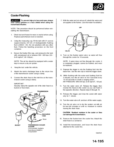
>> Download RL9604S14195A documenatation <<
Text preview - extract from the document
               Main Menu                Table of Contents


Cooler Flushing
              To prevent injury to face and eyes, always       7. With the water and air valves off, attach the water and
wear safety glasses or a face shield when using the               air supplies to the flusher. (Use hot water if available.)
transmission flusher.
                                                                                          OFF
NOTE: This procedure should be performed before rein-
stalling the transmission.

1.   Check tool and hoses for wear or cracks before using.
     Replace parts that are worn or cracked.

2.   Using the measuring cup, fill the tank with 21 ounces
     (approximately 2/3 full) of biodegradable flushing
     fluid (J35944 - 20). Do not substitute with any other
     fluid. Follow the handling procedure on the fluid
     container.
                                                                     VALVE
3.   Secure the flusher filler cap, and pressurize the tank
     with compressed air to between 550 - 829 kpa (5.6 -       8. Turn on the flusher water valve so water will flow
     8.45 kgf/cm2, 80-120psi).                                    through the cooler for 10 seconds.

     NOTE: The air line should be equipped with a water           NOTE: If water does not flow through the cooler, it
     trap to ensure a dry air system.                             is completely plugged, cannot be flushed, and must
                                                                  be replaced.
4.   Hang the tool under the vehicle.
                                                               9. Depress the trigger to mix the flushing fluid into the
5.   Attach the tank's discharge hose to the return line          water flow. Use the wire clip to hold the trigger down.
     of the transmission cooler using a clamp.
                                                              10. While flushing with the water and flushing fluid for
6.   Connect the drain hose to the inlet line on the trans-       2 minutes, turn the air valve on for 5 seconds every
     mission cooler using a clamp.                                15-20 seconds to create a surging action.
                                                                  AIR PRESSURE: MAX 845 kpa (8.45 kgf/cm2, 120 psi)
     IMPORTANT:
     Securely clamp the opposite end of the drain hose to a   11. Turn the water valve off. Release the trigger, then
     bucket or floor drain.                                       reverse the hoses to the cooler so you can flush in
                                                                  the opposite direction. Repeat steps 8 through 10.
                                     TRANSMISSION
                                                              12. Release the trigger, and rinse the cooler with water
                                                                  only for 1 minute.

                                                              13. Turn the water valve off, and turn off the water supply.

                                                              14. Turn the air valve on to dry the system out with air
                                                                  for two full minutes or until no moisture is visible
                                                                  leaving the drain hose.

                                                                  CAUTION: Residual moisture in the cooler or lines
                                           DISCHARGE              can damage the transmission.
                                           HOSE

                                            Water             15. Remove the flusher from the cooler line. Attach the
                                                                  drain hose to a container.

      BUCKET            TRANSMISSION COOLER                   16. Install the transmission, and leave the drain hose
                        FLUSHER                                   attached to the cooler line.
                        Commercially Available
                        Kent-Moore J38405-A
                        or equivalent
                Main Menu                  Table of Contents

Transmission
 Cooler Flushing (cont'd)
 17. Make sure the transmission is in the     position.
     Then fill the transmission with ATF, and run the
     engine for 30 seconds or until approximately 0.95
     (1.0 US qt., 0.8 Imp qt.) is discharged.

 18. Remove the drain hose, and reconnect the cooler
     return hose to the transmission (see next column).

 19. Refill the transmission with the recommended ATF
     to the proper level (see page 14-108).

 TOOL MAINTENANCE

 1.     Empty and rinse after each use. Fill the can with water
        and pressurize the can. Flush the discharge line to
        ensure that the unit is clean.

 2.     If discharge liquid does not foam, the orifice may be
        blocked.

 3.     To clean, disconnect the plumbing from the tank at
        the large coupling nut.


      FILLER CAP                     FILTER       COUPLING
                                                  NUT


                                                        ORIFICE
                                   O-RING


 4.     Remove the in-line filter from the discharge side and
        clean if necessary.

 5. The fluid orifice is located behind the filter.
    Clean it with the pick stored in the bottom of the
    tank handle, or blow it clean with air. Securely
    reassemble all parts.
◦ Jabse Service Manual Search 2026 ◦ Jabse Pravopis ◦ onTap.bg ◦ Other service manual resources online : Fixya ◦ eServiceinfo