Service Manuals, User Guides, Schematic Diagrams or docs for : . Car Manuals Acura 3.5RL 1996-2004 Approved srm RL9604S15026A

<< Back | Home

Most service manuals and schematics are PDF files, so You will need Adobre Acrobat Reader to view : Acrobat Download Some of the files are DjVu format. Readers and resources available here : DjVu Resources
For the compressed files, most common are zip and rar. Please, extract files with Your favorite compression software ( WinZip, WinRAR ... ) before viewing. If a document has multiple parts, You should download all, before extracting.
Good luck. Repair on Your own risk. Make sure You know what You are doing.


Image preview - the first page of the document
RL9604S15026A


>> Download RL9604S15026A documenatation <<

Text preview - extract from the document
                  Main Menu                  Table of Contents


Differential Assembly
 Installation
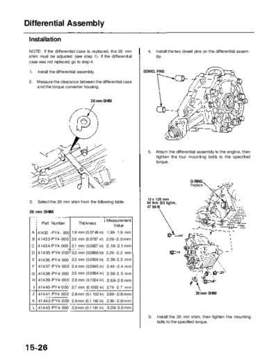
 NOTE: If the differential case is replaced, the 26 mm             4.   Install the two dowel pins on the differential assem-
 shim must be adjusted (see step 1). If the differential                bly.
 case was not replaced, go to step 4.

 1.     Install the differential assembly.                       DOWEL PINS

 2.    Measure the clearance between the differential case
       and the torque converter housing.


                                       26 mm SHIM


                                                                   5.   Attach the differential assembly to the engine, then
                                                                        tighten the four mounting bolts to the specified
                                                                        torque.


                                                                                           O-RING.
                                                                                           Replace.


                                                                   12 x 1.25 mm
 3.     Select the 26 mm shim from the following table.           64 N-m (6.5 kgf-m,
                                                                  47 Ibf-ft)
 26 mm SHIM

                                               Measurement
          Part Number           Thickness
                                                  Value
  A 41432 -PY4- 000 1.9 mm (0.07 48 in) 1.99- 1.9 mm
  B 41433-PY4-000 2.0 mm (0.0787 in) 2.09 - 2.0 mm
  C 41434-PY4-000 2.1 mm (0.0827 in) 2.19-2.1 mm
  D 41435-PY4-000 2.2 mm (0.0866 in) 2.29 -2.2 mm
  E 41436-PY4-000 2.3 mm (0.0906 in) 2.39-2.3 mm
  F 41437-PY4-000 2.4 mm (0.0945 in) 2.49 -2.4 mm
  G 41438-PY4-000 2.5 mm (0.0984 in) 2.59-2.5 mm
  H 41439-PY4-000 2.6 mm (0.1024 in) 2.69-2.6 mm
      I 41440-PY4-000 2.7 mm (0.1063 in) 2.79 -2.7 mm
  J 41441-PY4-000 2.8 mm (0.1 102 in) 2.89 - 2.8 mm                                           26 mm SHIM
  K 41442-PY4-000 2.9 mm (0.1 142 in) 2.99 - 2.9 mm
  L 41443-PY4-000 3.0 mm (0.1 181 in) 3.09-3.0 mm

                                                                   6.   Install the 26 mm shim, then tighten the mounting
                                                                        bolts to the specified torque.
                 Main Menu                   Table of Contents


7.    Install the right engine mount.                              9. Remove the chain hoist.

                                                                  10. Install the engine stop mount bracket bolts.
       RIGHT ENGINE                     10 x 1.25 mm
       MOUNT                            38 N-m (3.9 kgf-m,
                                        28 Ibf-ft)

                                                                    ENGINE STOP
                                                                    MOUNTS


                                                                            12 x 1.25 mm
                           10 x 1.25 mm                                     74 N-m (7.5 kgf-m,
                           38 N-m (3.9 kgf-m,                               54 Ibf-ft)
                           28 Ibf-ft)


8.    Install the right engine mount bracket, then right
      and left engine mount bracket nuts.                         11. Apply Super High Temp Urea Grease (P/N 08798 -
                                                                      9002) to the splines of the extension shaft, then
                                  12 x 1.25 mm                        install the new set ring.
     10 x 1.25 mm                 64 N-m (6.5 kgf-m,
     38 N-m (3.9 kgf-m,           47 Ibf-ft)
     28 Ibf-ft)                              RIGHT ENGINE
                                             MOUNT BRACKET


                                                                 SET RING
                                                                 Replace.
                                          12 x 1.25 mm
            Apply liquid gasket           64 N-m (6.5 kgf-m,
            (P/N 08718 -0001)             47 Ibf-ft)


                                                                                                                 15-27
                  Main Menu                Table of Contents


Differential Assembly
 Installation (cont'd)
 12. Install the extension shaft using the special tool as     15. Install the right exhaust manifold cover, then install
     shown.                                                        the breather tube to the clamp.

     NOTE: Push the extension shaft in the secondary
     driven gear shaft until the extension shaft stops.


                                             SET RING


                                                                                                                   CLAMP
                                                               8 x 1.25 mm
                                                               22 N-m (2.2 kgf-m,
                                                               16 Ibf-ft)                                          BREATHER
                                                                                                                   TUBE
                                              EXTENSION
      EXTENSION SHAFT                         SHAFT
      INSTALLER
      07MAF-PY40100 or
      07MAF-PY40101                                              RIGHT EXHAUST
                                                                 MANIFOLD COVER


 13. Fill the secondary gear with Super High Temp Urea
     Grease (P/N 08798 - 9002).
                                                               16. Install the power steering pump, then adjust the
                                                                   belt tension of pump belt (see section 17).
       O-RING
       Replace.                       12- 14 g (0.4 -0.5 oz)                                     22 N-m (2.2 kgf-m, 16 Ibf-ft)


                                                                                                               POWER
                                                                                                               STEERING
                                                                                                               PUMP


      36 mm SEALING BOLT
      78 N-m (8.0 kgf-m, 58 Ibf-ft)


                                                                 ADJUSTING                                  44 N-m (4.5 kgf-m,
                                                                 BOLT                                       33 Ibf-ft)
 14. Install the new O-ring in the groove of the 36 mm
     sealing bolt, then install the 36 mm sealing bolt.

      NOTE: Shift the transmission into the [P] position to
      lock the secondary gear.
               Main Menu                   Table of Contents


17. Install the air cleaner housing assembly.                  19. Remove the steering gearbox mounting bolts, then
                                                                   install the lower plate and the steering gearbox
  6 x 1.0 mm                                                       mounting bolts.
  9.8 N-m (1.0 kgf-m, 7.2 Ibf-ft)

                                       AIR CLEANER                                          STEERING GEARBOX
                                       HOUSING ASSEMBLY                                     MOUNTING BOLTS
                                                                                            59 N-m (6.0 kgf-m,
                                                                                            43 Ibf-ft)


                                                                                                       LOWER
                                                                                                       PLATE


                                                                10 x 1.25 mm
                                                                38 N-m (3.9 kgf-m,
                                                                28 Ibf-ft)


18. Install the vehicle speed sensor (VSS)/power steer-
    ing speed sensor, then connect the VSS connector.          20. Install the driveshafts and the intermediate shaft
                                                                   (see section 16).
      6 x 1.0 mm
      12 N-m (1.2 kgf-m, 8.7 Ibf-ft)                               CAUTION: While installing the driveshaft and the
                                        VSS CONNECTOR              intermediate shaft in the differential, be sure not to
                                                                   allow dust and other foreign particles to enter into
                                                                   the differential.

                                                               21. Install the damper fork, then install the right and left
                                                                   ball joints to the each lower arm with the castle nuts
                                                                   and new cotter pins (see section 18).


          O-RING
          Replace.      VSS/POWER STEERING
                        SPEED SENSOR
                 Main Menu                  Table of Contents


Differential Assembly
 Installation (cont'd)
 22. Install the splash shield.


                                    SPLASH SHIELD

       6 x 1.0 mm
       9.8 N-m (1.0 kgf-m, 7.2 Ibf-ft)


 23. Refill the differential with the recommended oil (see
     page 15-4).


◦ Jabse Service Manual Search 2024 ◦ Jabse PravopisonTap.bg ◦ Other service manual resources online : FixyaeServiceinfo