Service Manuals, User Guides, Schematic Diagrams or docs for : . Car Manuals Acura 3.5RL 1996-2004 Approved srm RL9604S19014A
<< Back | HomeMost service manuals and schematics are PDF files, so You will need Adobre Acrobat Reader to view : Acrobat Download Some of the files are DjVu format. Readers and resources available here : DjVu Resources
For the compressed files, most common are zip and rar. Please, extract files with Your favorite compression software ( WinZip, WinRAR ... ) before viewing. If a document has multiple parts, You should download all, before extracting.
Good luck. Repair on Your own risk. Make sure You know what You are doing.
Image preview - the first page of the document

>> Download RL9604S19014A documenatation <<
Text preview - extract from the document
              Main Menu                     Table of Contents


Master Cylinder/Brake Booster
 Removal/Installation
 CAUTION:                                                                   9. Remove the four brake booster mounting nuts.
   Be careful not to bend or damage the brake lines
   when removing the master cylinder.                                      10. Pull the brake booster forward until the clevis is
   Do not spill brake fluid on the vehicle; it may damage                      clear of the bulkhead.
   the paint; if brake fluid does contact the paint, wash
   it off immediately with water.                                          11. Remove the brake booster from the engine com-
   To prevent spills, cover the hose joints with rags or                       partment.
   shop towels.
                                                                           12. Install the brake booster and master cylinder in the
 1.   Disconnect the brake fluid level switch connectors.                      reverse order of removal.

 2.   Remove the reservoir cap from the master cylinder.                         CAUTION:
                                                                                   When connecting the brake lines, make sure
 3.   Remove the brake fluid from the master cylinder                              there is no interference between the brake lines
      reservoir with a syringe.                                                    and other parts.
                                                                                   Be careful not to bend or damage the brake lines
 4.   Disconnect the brake lines from the master cylinder.                         when installing the master cylinder.

 5.   Remove the master cylinder mounting nuts.                                  NOTE: If replacing the master cylinder or brake
                                                                                 booster, check and adjust the pushrod clearance
 6.   Remove the master cylinder from the brake booster.                         before installing the master cylinder (see page 19-15).

 7.   Disconnect the vacuum hose from the brake booster.                   13. Fill the master cylinder reservoir, and bleed the
                                                                               brake system (see page 19-8).
 8.   Remove the cotter pin and clevis pin from the clevis.
                                                                           14. After installation, check the brake pedal height and
      CAUTION: Do not disconnect the clevis by remov-                          brake pedal free play (see page 19-5), and adjust if
      ing it from the operating rod of the brake booster. If                   necessary.
      the clevis is loosened, adjust the pushrod length
      before installing the brake booster (see page 19-16).

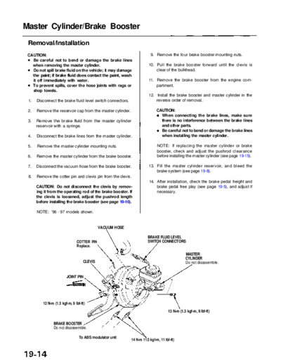
      NOTE: '96 - 97 models shown.


                                            VACUUM HOSE

                                                                           BRAKE FLUID LEVEL
                               COTTER PIN                                  SWITCH CONNECTORS
                               Replace.
                                                                                                    MASTER
                                                                                                    CYLINDER
                                   CLEVIS                                                           Do not disassemble.


                        JOINT PIN


         12 N-m (1.3 kgf-m, 9 Ibf-ft)
                                                                                         13 N-m (1.3 kgf-m, 9 Ibf-ft)


                BRAKE BOOSTER
                Do not disassemble.

                                 To ABS modulator unit
                                                                14 N-m 11.5 kgf-m, 11 Ibf-ft)
◦ Jabse Service Manual Search 2024 ◦ Jabse Pravopis ◦ onTap.bg ◦ Other service manual resources online : Fixya ◦ eServiceinfo