Service Manuals, User Guides, Schematic Diagrams or docs for : . Car Manuals Acura 3.5RL 1996-2004 Approved srm RL9604S19015B
<< Back | HomeMost service manuals and schematics are PDF files, so You will need Adobre Acrobat Reader to view : Acrobat Download Some of the files are DjVu format. Readers and resources available here : DjVu Resources
For the compressed files, most common are zip and rar. Please, extract files with Your favorite compression software ( WinZip, WinRAR ... ) before viewing. If a document has multiple parts, You should download all, before extracting.
Good luck. Repair on Your own risk. Make sure You know what You are doing.
Image preview - the first page of the document
>> Download RL9604S19015B documenatation <<
Text preview - extract from the document
Main Menu   Table of Contents


                                  Pushrod Clearance Adjustment
                                  NOTE: Master cylinder pushrod-to-piston clearance must
                                  be checked and adjustments made, if necessary, before
                                  installing the master cylinder.

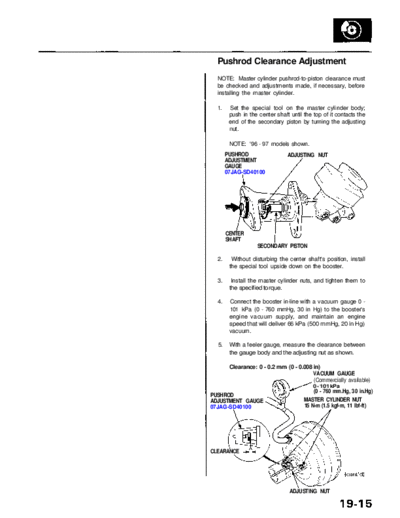
                                  1.    Set the special tool on the master cylinder body;
                                        push in the center shaft until the top of it contacts the
                                        end of the secondary piston by turning the adjusting
                                        nut.

                                        NOTE: '96 - 97 models shown.
                                       PUSHROD                  ADJUSTING NUT
                                       ADJUSTMENT
                                       GAUGE
                                       07JAG-SD40100


                                       CENTER
                                       SHAFT
                                                   SECONDARY PISTON

                                  2.     Without disturbing the center shaft's position, install
                                        the special tool upside down on the booster.

                                  3.     Install the master cylinder nuts, and tighten them to
                                        the specified torque.

                                  4.    Connect the booster in-line with a vacuum gauge 0 -
                                        101 kPa (0 - 760 mmHg, 30 in Hg) to the booster's
                                        engine vacuum supply, and maintain an engine
                                        speed that will deliver 66 kPa (500 mmHg, 20 in Hg)
                                        vacuum.

                                  5.    With a feeler gauge, measure the clearance between
                                        the gauge body and the adjusting nut as shown.

                                        Clearance: 0 - 0.2 mm (0 - 0.008 in)
                                                                         VACUUM GAUGE
                                                                         (Commercially available)
                                                                           0 - 101 kPa
                                                                           (0 - 760 mm.Hg, 30 in.Hg)
                                PUSHROD
                                ADJUSTMENT GAUGE                       MASTER CYLINDER NUT
                                07JAG-SD40100                          15 N-m (1.5 kgf-m, 11 Ibf-ft)


                                CLEARANCE


                                                                 ADJUSTING NUT
                 Main Menu                  Table of Contents


Master Cylinder/Brake Booster
 Pushrod Clearance Adjustment
 (cont'd)
 NOTE: If the clearance between the gauge body and
 adjusting nut is 0.2 mm (0.008 in), the pushrod-to-piston
 clearance is 0 mm. However, if the clearance between
 the gauge body and adjusting nut is 0 mm, the pushrod-
 to-piston clearance is 0.2 mm (0.008 in) or more.
 Therefore it must be adjusted and rechecked.

 6.   If the clearance is incorrect, remove the tool, and
      adjust the clearance by holding the pushrod and
      turning the adjuster in or out.

      CAUTION: Do not pull the pushrod out of the brake
      booster.

      NOTE: Adjust the clearance while the specified vac-
      uum is applied to the booster.


               ADJUSTER


                    PUSHROD
 7.   Adjust the pushrod length as shown if the booster
      is removed.


                                             CLEVIS
                                       LOCKNUT
                                       15 N-m
                                       (1.5 kgf-m,
                                       11 Ibf-ft)
                              PUSHROD
 8.    Install the master cylinder (see page 19-14).
◦ Jabse Service Manual Search 2026 ◦ Jabse Pravopis ◦ onTap.bg ◦ Other service manual resources online : Fixya ◦ eServiceinfo