Service Manuals, User Guides, Schematic Diagrams or docs for : . Car Manuals Acura 3.5RL 1996-2004 Approved srm RL9604S19100A
<< Back | HomeMost service manuals and schematics are PDF files, so You will need Adobre Acrobat Reader to view : Acrobat Download Some of the files are DjVu format. Readers and resources available here : DjVu Resources
For the compressed files, most common are zip and rar. Please, extract files with Your favorite compression software ( WinZip, WinRAR ... ) before viewing. If a document has multiple parts, You should download all, before extracting.
Good luck. Repair on Your own risk. Make sure You know what You are doing.
Image preview - the first page of the document

>> Download RL9604S19100A documenatation <<
Text preview - extract from the document
              Main Menu                 Table of Contents


Modulator Unit
 Installation                                                Wire Harness Replacement
 NOTE: This procedure is for modulator unit replacement.     1.   Remove the modulator unit (see page 19-99).

 1.   Fill the modulator reservoir to the MAX line.          2.   Remove the cover, then remove the wire harness.

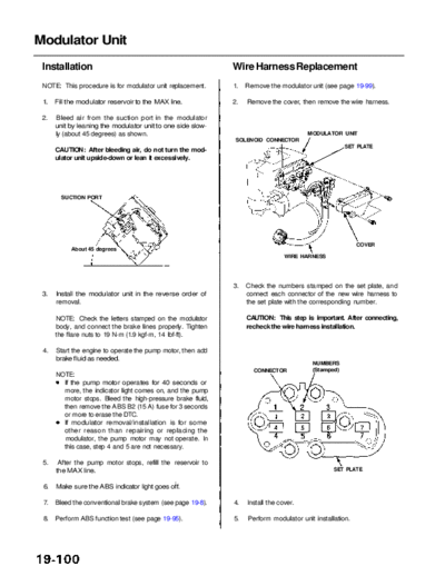
 2.    Bleed air from the suction port in the modulator
      unit by leaning the modulator unit to one side slow-
      ly (about 45 degrees) as shown.                                                  MODULATOR UNIT
                                                              SOLENOID CONNECTOR
                                                                                                    SET PLATE
      CAUTION: After bleeding air, do not turn the mod-
      ulator unit upside-down or lean it excessively.


        SUCTION PORT


                                                                                                         COVER
           About 45 degrees
                                                                                WIRE HARNESS


                                                             3.   Check the numbers stamped on the set plate, and
 3.   Install the modulator unit in the reverse order of          connect each connector of the new wire harness to
      removal.                                                    the set plate with the corresponding number.

      NOTE: Check the letters stamped on the modulator            CAUTION: This step is important. After connecting,
      body, and connect the brake lines properly. Tighten         recheck the wire harness installation.
      the flare nuts to 19 N-m (1.9 kgf-m, 14 Ibf-ft).

 4.   Start the engine to operate the pump motor, then add
      brake fluid as needed.
                                                                                        NUMBERS
                                                                    CONNECTOR           (Stamped)
      NOTE:
        If the pump motor operates for 40 seconds or
        more, the indicator light comes on, and the pump
        motor stops. Bleed the high-pressure brake fluid,
        then remove the ABS B2 (15 A) fuse for 3 seconds
        or more to erase the DTC.
        If modulator removal/installation is for some
        other reason than repairing or replacing the
        modulator, the pump motor may not operate. In
        this case, step 4 and 5 are not necessary.

 5.    After the pump motor stops, refill the reservoir to
      the MAX line.                                                                             SET PLATE


 6.   Make sure the ABS indicator light goes off.

 7.   Bleed the conventional brake system (see page 19-8).   4.   Install the cover.

 8.   Perform ABS function test (see page 19-95).            5.   Perform modulator unit installation.
◦ Jabse Service Manual Search 2024 ◦ Jabse Pravopis ◦ onTap.bg ◦ Other service manual resources online : Fixya ◦ eServiceinfo