Service Manuals, User Guides, Schematic Diagrams or docs for : . Car Manuals Acura 3.5RL 1996-2004 Approved srm RL9604S19107A
<< Back | HomeMost service manuals and schematics are PDF files, so You will need Adobre Acrobat Reader to view : Acrobat Download Some of the files are DjVu format. Readers and resources available here : DjVu Resources
For the compressed files, most common are zip and rar. Please, extract files with Your favorite compression software ( WinZip, WinRAR ... ) before viewing. If a document has multiple parts, You should download all, before extracting.
Good luck. Repair on Your own risk. Make sure You know what You are doing.
Image preview - the first page of the document
>> Download RL9604S19107A documenatation <<
Text preview - extract from the document
Main Menu Table of Contents
Anti-lock Brake System (ABS)
Features/Construction
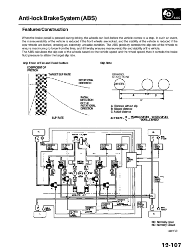
When the brake pedal is pressed during driving, the wheels can lock before the vehicle comes to a stop. In such an event,
the maneuverability of the vehicle is reduced if the front wheels are locked, and the stability of the vehicle is reduced if the
rear wheels are locked, creating an extremely unstable condition. The ABS precisely controls the slip rate of the wheels to
ensure maximum grip force from the tires, and it thereby ensures maneuverability and stability of the vehicle.
The ABS calculates the slip rate of the wheels based on the vehicle speed and the wheel speed, then it controls the brake
fluid pressure to attain the target slip rate.
Grip Force of Tire and Road Surface Slip Rate
COEFFICIENT OF
FRICTION
TARGET SLIP RATE BRAKING
START POINT
ROTATIONAL
DIRECTION
RADIAL
DIRECTION
OF THE
ROTATIONAL A: Distance without slip
DIRECTION B: Slipped distance
C: Actual distance
SLIP RATE
NO: Normally Open
NC: Normally Closed
Main Menu Table of Contents
Anti-lock Brake System (ABS)
Features/Construction (cont'd)
ABS Control
The ABS control unit detects the wheel speed based on the wheel sensor signal it received, then it calculates the vehicle
speed based on the detected wheel speed. The control unit detects the vehicle speed during deceleration based on the
rate of deceleration.
The ABS control unit calculates the slip rate of each wheel, and it transmits the control signal to the modulator unit
solenoid valve when the slip rate is high.
The pressure reduction control has 3-modes: pressure reduction, pressure retaining, and pressure intensifying.
ABS CONTROL UNIT
Main Menu Table of Contents
Self-diagnosis
1. The ABS control unit is equipped with a main CPU and a sub CPU, that check each other for problems.
2. The CPUs check the circuit of the system.
3. Self-diagnosis can be classified into 2 categories.
Initial diagnosis: Performed right after the engine starts and until the ABS indicator goes off.
Regular diagnosis: Performed right after the initial diagnosis until the ignition switch is turned OFF.
4. When a problem is detected by self-diagnosis, the system:
Turns the fail-safe relay OFF
Turns the solenoid valve OFF
Turns the pump motor OFF
Turns the ABS indicator ON
Self-diagnosis Table
Detection
Timing
Diagnostic Trouble
Diagnosis
Diagnosis
Detection Item Fail-safe Mode
Code(DTC)
Regular
Initial
11, 13, 15, 17 Wheel sensor (open/short to body ground/short to power) O A
12,14,16,18 Wheel sensor (electrical noise/intermittent Interruption) O S, A and L, S and L
21-24 Pulser O A and L
31-38 Solenoid (short to body ground/short to wire) O O S
41-44 Wheel lock O A and L
51 Motor lock O S and L
52 Motor stuck OFF O A and L
53 Motor stuck ON O O A and L
54 Fall-safe relay O S
61 Low ignition voltage O B
62 High ignition voltage O B
71 Different diameter tire O S
81 Central Processing Unit (CPU) diagnosis, and ROM/RAM diagnosis O O S
Operation Mode Table
Operation
Description ABS Indicator
Mode
Regular
Operation in normal condition OFF
operation
Fail-safe Comes ON when a
The ABS control unit turns the system off when the control unit detects a problem.
mode-S problem is detected.
If the ABS control unit detects a malfunction during an emergency stop, it will turn off the malfunc-
Fail-safe Comes ON when a
tioning component, and continue to modulate the rest of the ABS system until the vehicle comes to
mode-A problem is detected.
a stop. At that, the entire system will be turned off until the problem goes away.
The ABS control unit stores a DTC in back-up memory when it detects a problem. If a problem is
Fail-safe
detected when the ignition switch is turned ON (II), the ABS control unit will turn the system off. If ON
mode-L
the problem goes away, the ABS control unit will turn the system on again.
Fail-safe The ABS control unit will turn the system off if ignition voltage drops, and will turn on again when Comes ON when a
mode-B ignition voltage returns to normal. problem is detected.
On-board Diagnosis Function
The ABS control unit is connected to the 16P Data Link Connector.
The ABS can be diagnosed with the Honda PGM Tester.
The ALB Checker cannot be used with this system. For air bleeding, and checking wheel sensor signals, use the Honda
PGM Tester. See the Honda PGM Tester user's manuals for specific operating instructions.
Main Menu Table of Contents
Anti-lock Brake System (ABS)
Features/Construction (cont'd)
ABS Modulator
The ABS modulator consists of the inlet solenoid valve, outlet solenoid valve, reservoir, pump, pump motor and the
damping chamber.
The modulator reduces the caliper fluid pressure directly. It is a circulating-type modulator because the brake fluid circulates
through the caliper, reservoir and the master cylinder.
The hydraulic control has three modes: pressure reduction, pressure retaining and pressure intensifying.
The hydraulic circuit is the independent four channel-type, one channel for each wheel.
SOLENOID VALVE
PUMP
MOTOR
IN: INLET VALVE (NORMALLY OPEN)
Pressure intensifying mode: Inlet valve open, outlet valve closed OUT: OUTLET VALVE (NORMALLY CLOSED)
Master cylinder fluid is pumped out to the caliper.
Pressure retaining mode: Inlet valve closed, outlet valve closed
Caliper fluid is retained by the inlet valve and outlet valve.
Pressure reduction mode: Inlet valve closed, outlet valve open
Caliper fluid flows through the outlet valve to the reservoir.
Motor operation mode: When starting the pressure reduction mode, the pump motor is ON.
When stopping ABS operation, the pump motor is OFF.
The reservoir fluid is pumped out by the pump, through the damping chamber, to the master
cylinder.
Main Menu Table of Contents
Wheel Speed and Modulator Control
SPEED VEHICLE SPEED
REFERENCE VEHICLE SPEED
WHEEL SPEED
TIME
PRESSURE
OUTLET
VALVE
INLET
VALVE
MOTOR
ON
OFF
When the wheel speed drops sharply below the vehicle speed, the inlet valve closes to retain the caliper fluid pressure.
When the wheel speed drops further, the outlet valve opens momentarily to reduce the caliper fluid pressure. The pump
motor starts at this time.
As the wheel speed is restored, the inlet valve opens momentarily to increase the caliper fluid pressure.
Wheel Sensor
The wheel sensors are the magnetic contactless type. As the gear pulser teeth rotate past the wheel sensor's magnetic
coil, AC current is generated. The AC frequency changes in accordance with the wheel speed. The ABS control unit detects
the wheel sensor signal frequency and thereby detects the wheel speed.
GEAR PULSER
WHEEL SENSOR at HIGH SPEED
at LOW SPEED
◦ Jabse Service Manual Search 2026 ◦ Jabse Pravopis ◦ onTap.bg ◦ Other service manual resources online : Fixya ◦ eServiceinfo