Service Manuals, User Guides, Schematic Diagrams or docs for : . Car Manuals Acura 3.5RL 1996-2004 Approved srm RL9604S19114A

<< Back | Home

Most service manuals and schematics are PDF files, so You will need Adobre Acrobat Reader to view : Acrobat Download Some of the files are DjVu format. Readers and resources available here : DjVu Resources
For the compressed files, most common are zip and rar. Please, extract files with Your favorite compression software ( WinZip, WinRAR ... ) before viewing. If a document has multiple parts, You should download all, before extracting.
Good luck. Repair on Your own risk. Make sure You know what You are doing.


Image preview - the first page of the document
RL9604S19114A


>> Download RL9604S19114A documenatation <<

Text preview - extract from the document
               Main Menu                  Table of Contents


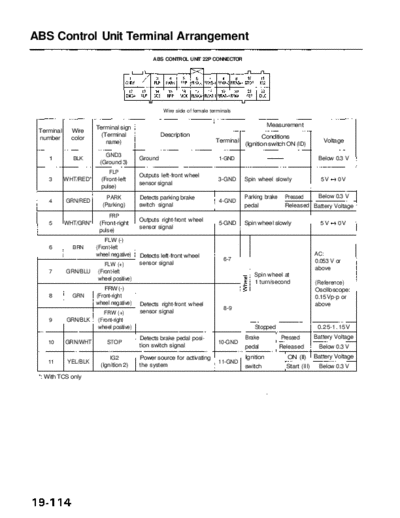
ABS Control Unit Terminal Arrangement
                                               ABS CONTROL UNIT 22P CONNECTOR


                                                    Wire side of female terminals


                       Terminal sign                                                            Measurement
 Terminal     Wire
                         (Terminal                 Description                              Conditions
 number       color                                                       Terminal                                 Voltage
                           name)                                                     (Ignition switch ON (ID)
                          GND3
    1         BLK                         Ground                           1-GND                                 Below 0.3 V
                        (Ground 3)
                              FLP
                                          Outputs left-front wheel
    3       WHT/RED*       (Front-left                                     3-GND     Spin wheel slowly            5V    0V
                                          sensor signal
                           pulse)
                             PARK         Detects parking brake                      Parking brake    Pressed   Below 0.3 V
    4       GRN/RED                                                        4-GND
                           (Parking)      switch signal                              pedal            Released Battery Voltage
                            FRP
                                          Outputs right-front wheel
    5       WHT/GRN*    (Front-right                                       5-GND     Spin wheel slowly            5V    0V
                                          sensor signal
                        pulse)
                           FLW (-)
    6         BRN      (Front-left
                       wheel negative)    Detects left-front wheel                                              AC:
                                                                             6-7                                0.053 V or
                          FLW (+)         sensor signal
                                                                                                                above
    7       GRN/BLU    (Front-left
                                                                                        Spin wheel at
                       wheel positive)
                                                                                        1 turn/second           (Reference)
                          FRW (-)                                                                               Oscilloscope:
    8         GRN      (Front-right                                                                             0.15Vp-p or
                       wheel negative)    Detects right-front wheel                                             above
                                                                             8-9
                          FRW (+)         sensor signal
    9       GRN/BLK    (Front-right
                       wheel positive)                                                  Stopped                  0.25-1. 15V
                                          Detects brake pedal posi-                  Brake           Pressed    Battery Voltage
    10      GRN/WHT          STOP                                          10-GND
                                          tion switch signal                         pedal           Released     Below 0.3 V
                               IG2        Power source for activating                Ignition          ON (II) Battery Voltage
    11       YEL/BLK                                                       11-GND
                           (Ignition 2)   the system                                 switch            Start (III) Below 0.3 V
 *: With TCS only
             Main Menu                   Table of Contents


                                                                                         Measurement
Terminal     Wire      Terminal sign
                                                  Description                            Conditions
number       color    (Terminal name)                                 Terminal                                   Voltage
                                                                                 (Ignition switch ON (ID)
                           GND4
   12        BLK                         Ground                       12-GND                                   Below 0.3 V
                         (Ground 4)
                           RLP
                                         Outputs left-rear wheel
   13      GRY/WHT*      (Rear-left                                   13-GND      Spin wheel slowly             5V    0V
                                         sensor signal
                         pulse)
                           SCS           Detects service check con-              SCS service Connected         Below 0.3 V
   14        RED      (Service check     nector signal (DTC indica-   14-GND
                                                                                 connector     Disconnected     About 5 V
                      signal)            tion or DTC erasure)
                            RRP
                                         Outputs right-rear wheel
   15      GRY/BLK*      (Rear-right                                  15-GND     Turn wheel slowly              5V    0V
                                         sensor signal
                         pulse)
                                                                                                ON     Battery Voltage
                           MCK           Detects pump motor drive                Pump motor ----------
   16        GRN                                                      16-GND                    OFF     Below 0.3 V
                       (Motor check)     signal
                                                                                 Remove MCK fuse               About 10 V
                          RLW (+)
   17       LT BLU     (Rear-left
                       wheel positive)   Detects left-rear wheel                                              AC:
                                                                       17-18                                  0.053 V or
                         RLW (-)         sensor signal
                                                                                                              above
   18        GRY      (Rear-left
                                                                                    Turn wheel at
                      wheel negative)
                                                                                    1 turn/second             (Reference)
                         RRW (+)                                                                              Oscilloscope:
   19      GRN/YEL     (Rear-right                                                                            0.15 Vp-p or
                       wheel positive)   Detects right-rear wheel                                             above
                                                                       19-20
                          RRW (-)        sensor signal
   20      BLU/YEL     (Rear-right
                       wheel negative)                                               Stopped                  0.25 -1.15V
                                         Drives fail-safe relay
                                         (Fail-safe relay is turned                               Warning      Below 0.3 V
                            FSR
                                         OFF to shut off the power
   21      YEL/GRN       (Fail-safe                                   21-GND
                                         source to the solenoid and
                         relay)
                                         pump motor relay when                                     Normal      About 1 1 V
                                         problem occurs.)
                            DLC
                                         Communicates with the
   22        RED         (Data link                                   22-GND
                                         Honda PGM Tester
                         connector)
*: With TCS only
              Main Menu                  Table of Contents


ABS Control Unit Terminal Arrangement
                                               ABS CONTROL UNIT 12P CONNECTOR


                                                   Wire side of female terminals

                                                                                             Measurement
 Terminal     Wire     Terminal sign
                                                  Description                               Conditions
 number       color   (Terminal name)                                    Terminal                                 Voltage
                                                                                    (Ignition switch ON (ID)
                                   Drives ABS indicator                                               ON           4-6V
                        WALP       (Turns the indicator drive
    1       BLU/WHT                                                        1-GND    ABS indicator
                    (Warning lamp) transistor to ON, then turns
                                                                                                      OFF       Below 0.3 V
                                   off the indicator)
                            GND1
    2         BLK                        Ground                            2-GND                                Below 0.3 V
                          (Ground 1)
                           RR-OUT
                                         Drives right-rear outlet
    3       BLK/ORN       (Rear-right                                      3-GND
                                         solenoid valve
                          outlet)
                                                                                               OFF             Battery Voltage
                            FL-OUT
                                         Drives left-front outlet
    4       YEL/BLU        (Front-left                                     4-GND
                                         solenoid valve
                           outlet)
                            RL-OUT
                                         Drives left-rear outlet
    5       YEL/WHT        (Rear-left                                      5-GND
                                         solenoid valve
                           outlet)
                                                                                                ON              Below 0.3 V
                            FR-OUT
                                         Drives right-front outlet
    6       YEL/BLK       (Front-right                                     6-GND
                                         solenoid valve
                          outlet)
                            GND2
    7         BLK                        Ground                            7-GND                                Below 0.3 V
                          (Ground 2)
                             RR-IN
                                         Drives right-rear inlet
    8         YEL         (Rear-right                                      8-GND
                                         solenoid valve
                          inlet)
                                                                                               OFF             Battery Voltage
                              FL-IN
                                         Drives left-front inlet
    9       RED/BLU        (Front-left                                     9-GND
                                         solenoid valve
                           inlet)
                             RL-IN
                                         Drives left-rear inlet
    10      RED/WHT        (Rear-left                                     10-GND
                                         solenoid valve
                           inlet)
                                                                                                ON              Below 0.3 V
                              FR-IN
                                         Drives right-front inlet
    11      RED/BLK       (Front-right                                    11-GND
                                         solenoid valve
                          inlet)
                                                                                                      ON        Below 1.0V
                                                                                       OFF
                               PMR                                                                    OFF      Battery Voltage
    12      YEL/RED       (Pump motor    Drives pump motor relay          12-GND
                          relay)                                                                ON              Below 0.3 V


◦ Jabse Service Manual Search 2024 ◦ Jabse PravopisonTap.bg ◦ Other service manual resources online : FixyaeServiceinfo