Service Manuals, User Guides, Schematic Diagrams or docs for : . Car Manuals Acura 3.5RL 1996-2004 Approved srm RL9604S19200A

<< Back | Home

Most service manuals and schematics are PDF files, so You will need Adobre Acrobat Reader to view : Acrobat Download Some of the files are DjVu format. Readers and resources available here : DjVu Resources
For the compressed files, most common are zip and rar. Please, extract files with Your favorite compression software ( WinZip, WinRAR ... ) before viewing. If a document has multiple parts, You should download all, before extracting.
Good luck. Repair on Your own risk. Make sure You know what You are doing.


Image preview - the first page of the document
RL9604S19200A


>> Download RL9604S19200A documenatation <<

Text preview - extract from the document
      Main Menu   Table of Contents


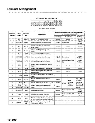
Terminal Arrangement


                       VSA CONTROL UNIT 42P CONNECTOR


                            Wire side of female terminals
           Main Menu                Table of Contents


                                                                            Measurement (With the VSA control unit 42P
Terminal    Wire       Terminal                                                     connector disconnected)
                                               Description
number      color        sign
                                                                            Terminals       Conditions            Voltage
                                  Power source for activating the                       Ignition switch ON        Battery
   23      YEL/BLK       IG2                                                 23-GND
                                  system                                                (II)                      Voltage
   24       WHT        CAN (+)    Communication signal
  25         YEL         PSM      Ground for the pressure sensor
   26        BLU         PSS      Detects pressure sensor signal
                                                                                        Press the VSA off
                        VSA                                                                                       Battery
   27      WHT/BLK                Detects VSA off switch signal              27-GND     switch with the igni-
                       OFF SW                                                                                     Voltage
                                                                                        tion switch ON (II)
   28      GRN/BLU      FLS (+)   Detects left-front wheel sensor signal      28-13                             AC: 0.053 V
                                                                                                                or above
   29        GRY        RLS (-)   Detects left-rear wheel sensor signal       29-14                             Reference
                                                                                        Wheel
   30      BLU/YEL     RRS (-)                                                                                  Oscilloscope
                                  Detects right-rear wheel sensor signal      30-31                             0.15 Vp-p or
   31      GRN/YEL     RRS (+)                                                                                  above
                                  Detects brake pedal position switch                   Press the brake           Battery
   32      GRN/WHT      STOP                                                 32-GND
                                  signal                                                pedal                     Voltage
           LT GRN/                                                                      Ignition switch ON
   33                    VSA      Drives VSA system indicator                33-GND                              About 5 V
             RED                                                                        (ID
                                                                                        With the igni-            Battery
                                                                                        tion switch               Voltage
   36      GRN/WHT       BFL      Detects brake fluid level switch signal    36-GND     ON (II), the   ------
                                                                                        brake fluid                 0V
                                                                                        level is
                                                                                        With the
                                                                                        ignition    Pressed         0V
                                                                                        switch ON
   38      GRN/RED      PARK      Detects parking brake switch signal        38-GND
                                                                                        (II), park-
                                                                                                                  Battery
                                                                                        ing brake Released
                                                                                                                  Voltage
                                                                                        pedal is
                        YRSA      Power source for the yaw rate/lateral
   39        YEL
                         YU       acceleration sensor
   40        PNK       CAN (- )   Communication signal
   41        BLK        YRSS      Detects yaw rate sensor signal
   42        GRN         PSU      Power source for the pressure sensor


◦ Jabse Service Manual Search 2024 ◦ Jabse PravopisonTap.bg ◦ Other service manual resources online : FixyaeServiceinfo