Service Manuals, User Guides, Schematic Diagrams or docs for : . Car Manuals Acura 3.5RL 1996-2004 Approved srm RL9604S19269A
<< Back | HomeMost service manuals and schematics are PDF files, so You will need Adobre Acrobat Reader to view : Acrobat Download Some of the files are DjVu format. Readers and resources available here : DjVu Resources
For the compressed files, most common are zip and rar. Please, extract files with Your favorite compression software ( WinZip, WinRAR ... ) before viewing. If a document has multiple parts, You should download all, before extracting.
Good luck. Repair on Your own risk. Make sure You know what You are doing.
Image preview - the first page of the document

>> Download RL9604S19269A documenatation <<
Text preview - extract from the document
                Main Menu              Table of Contents


VSA Modulator-Control Unit
 Removal/Installation
 NOTE:
   Do not spill brake fluid on the vehicle; it may damage the paint; if brake fluid does contact the paint, wash it off imme-
   diately with water.
   Take care not to damage or deform the brake lines during removal and installation.
   To prevent the brake fluid from flowing, plug and cover the hose ends and joints with a shop towel or equivalent material.

 Removal
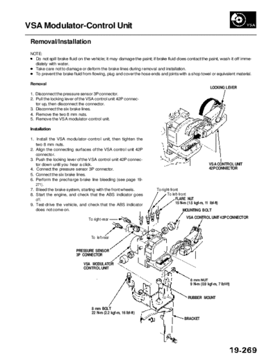
                                                                                                          LOCKING LEVER
 1. Disconnect the pressure sensor 3P connector.
 2. Pull the locking lever of the VSA control unit 42P connec-
    tor up, then disconnect the connector.
 3. Disconnect the six brake lines.
 4. Remove the two 8 mm nuts.
 5. Remove the VSA modulator-control unit.

 Installation

 1. Install the VSA modulator-control unit, then tighten the
    two 8 mm nuts.
 2. Align the connecting surfaces of the VSA control unit 42P
    connector.
 3. Push the locking lever of the VSA control unit 42P connec-
    tor down until you hear a click.                                                                     VSA CONTROL UNIT
 4. Connect the pressure sensor 3P connector.                                                            42P CONNECTOR
 5. Connect the six brake lines.
 6. Perform the precharge brake line bleeding (see page 19-
    271).
 7. Bleed the brake system, starting with the front wheels.            To right-front
 8. Start the engine, and check that the ABS indicator goes                   To left-front
    off.                                                                           FLARE NUT
 9. Test-drive the vehicle, and check that the ABS indicator                       15 N-m (1.5 kgf-m, 11 Ibf-ft)
    does not come on.                                                                   MOUNTING BOLT

                                 To right-rear                                            VSA CONTROL UNIT 42P CONNECTOR


                                   To left-rear


                            PRESSURE SENSOR
                            3P CONNECTOR

                               VSA MODULATOR
                               CONTROL UNIT

                                                                                             8 mm NUT
                                                                                             9 N-m (0.9 kgf-m, 7 Ibf-ft)


                                                                                           RUBBER MOUNT

                                   8 mm BOLT
                                   22 N-m (2.2 kgf-m, 16 Ibf-ft)
                                                                                         BRACKET
◦ Jabse Service Manual Search 2024 ◦ Jabse Pravopis ◦ onTap.bg ◦ Other service manual resources online : Fixya ◦ eServiceinfo