Service Manuals, User Guides, Schematic Diagrams or docs for : . Car Manuals Acura 3.5RL 1996-2004 Approved srm RL9604S20063A
<< Back | HomeMost service manuals and schematics are PDF files, so You will need Adobre Acrobat Reader to view : Acrobat Download Some of the files are DjVu format. Readers and resources available here : DjVu Resources
For the compressed files, most common are zip and rar. Please, extract files with Your favorite compression software ( WinZip, WinRAR ... ) before viewing. If a document has multiple parts, You should download all, before extracting.
Good luck. Repair on Your own risk. Make sure You know what You are doing.
Image preview - the first page of the document
>> Download RL9604S20063A documenatation <<
Text preview - extract from the document
Main Menu Table of Contents
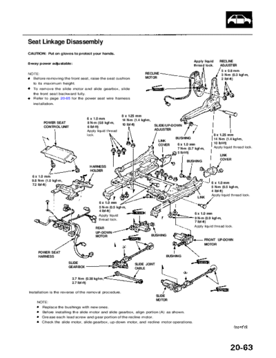
Seat Linkage Disassembly
CAUTION: Put on gloves to protect your hands.
Apply liquid RECLINE
8-way power adjustable: thread lock. ADJUSTER
5 x 0.8 mm
NOTE: RECLINE 3 N-m (0.3 kgf-m,
Before removing the front seat, raise the seat cushion MOTOR 2 Ibf-ft)
to its maximum height.
To remove the slide motor and slide gearbox, slide
the front seat backward fully.
Refer to page 20-65 for the power seat wire harness
installation.
8 x 1.25 mm
6 x 1.0 mm 14 N-m (1.4 kgf-m,
POWER SEAT 8 N-m (0.8 kgf-m,
10 Ibf-ft) SLIDE/UP-DOWN
CONTROL UNIT 6 Ibf-ft)
Apply liquid thread ADJUSTER
lock. 8 x 1.25 mm
BUSHING 14 N-m (1.4 kgf-m,
LINK
6 x 1.0 mm 10 Ibf-ft)
COVER
7 N-m (0.7 kgf-m, Apply liquid thread lock.
5 Ibf-ft)
LINK
BUSHING COVER
HARNESS
HOLDER
6 x 1.0 mm
9.8 N-m (1.0 kgf-m,
6 x 1.0 mm
7.2 Ibf-ft)
5 N-m (0.5 kgf-m,
4 Ibf-ft)
Apply liquid thread lock.
LINK
6 x 1.0 mm
5 N-m (0.5 kgf-m,
4 Ibf-ft)
Apply liquid 6 x 1.0 mm
thread lock. 9 N-m (0.9 kgf-m,
7 Ibf-ft)
Apply liquid thread lock.
REAR
UP-DOWN
MOTOR BUSHING
FRONT UP-DOWN
MOTOR
POWER SEAT
HARNESS BUSHING
SLIDE SLIDE JOINT
GEARBOX CABLE
3.7 N-m (0.38 kgf-m,
2.7 Ibf-ft)
Installation is the reverse of the removal procedure.
SLIDE
MOTOR
NOTE:
Replace the bushings with new ones.
Before installing the slide motor and slide gearbox, align portion (A) as shown.
Grease each lead screw and gear portion of the recline motor.
Check the slide motor, slide gearbox, up-down motor, and recline motor operations.
Main Menu Table of Contents
Front Seat
Seat Linkage Disassembly (cont'd)
4-way power adjustable:
NOTE: To remove the slide motor and slide gearbox, slide the front seat backward fully.
5 x 0.8 mm
3 N-m (0.3 kgf-m,
21 Ibf-ft)
RECLINE RECLINE
ADJUSTER MOTOR
8 x 1.25 mm
14 N-m (1.4 kgf-m, 8 x 1.25 mm
10 Ibf-ft) 14 N-m (1.4 kgf-m,
10 Ibf-ft)
6 x 1.0 mm
Apply liquid thread
8 N-m (0.8 kgf-m
lock. PIVOT
6 Ibf-ft)
Apply liquid BRACKET
thread lock. OUTER SLIDE
ADJUSTER
6 x 1.0 mm
8 N-m (0.8 kgf-m,
6 Ibf-ft) SEAT BELT
Apply liquid thread lock. BUCKLE
BRACKET
6 x 1.0 mm
9 N-m (0.9 kgf-m,
7 Ibf-ft)
Apply liquid INNER SLIDE
thread lock. ADJUSTER
10 x 1.25 mm
25 N-m (2.5 kgf-m,
SLIDE JOINT 18 Ibf-ft)
CABLE
6 x 1.0 mm
9 N-m (0.9 kgf-m,
7 Ibf-ft)
SLIDE Apply liquid thread lock.
GEARBOX
3.7 N-m (0.38 kgf-m,
2.7 Ibf-ft)
SLIDE
MOTOR
Installation is the reverse of the removal procedure.
NOTE:
Before installing the slide motor and slide gearbox, align portion as shown.
Grease the slide lead screws and gear portion of the recline motor.
Check the slide motor, slide gearbox, and recline motor operations.
◦ Jabse Service Manual Search 2026 ◦ Jabse Pravopis ◦ onTap.bg ◦ Other service manual resources online : Fixya ◦ eServiceinfo