Service Manuals, User Guides, Schematic Diagrams or docs for : . Car Manuals Acura 3.5RL 1996-2004 Approved srm RL9604S22058A
<< Back | HomeMost service manuals and schematics are PDF files, so You will need Adobre Acrobat Reader to view : Acrobat Download Some of the files are DjVu format. Readers and resources available here : DjVu Resources
For the compressed files, most common are zip and rar. Please, extract files with Your favorite compression software ( WinZip, WinRAR ... ) before viewing. If a document has multiple parts, You should download all, before extracting.
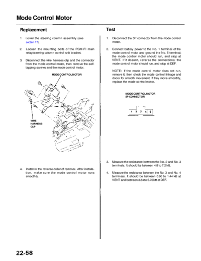
Good luck. Repair on Your own risk. Make sure You know what You are doing.
Image preview - the first page of the document

>> Download RL9604S22058A documenatation <<
Text preview - extract from the document
               Main Menu                  Table of Contents


Mode Control Motor
 Replacement                                                     Test
 1.   Lower the steering column assembly (see                    1.   Disconnect the 5P connector from the mode control
      section 17).                                                    motor.

 2.   Loosen the mounting bolts of the PGM-FI main               2.   Connect battery power to the No. 1 terminal of the
      relay/steering column control unit bracket.                     mode control motor and ground the No. 5 terminal;
                                                                      the mode control motor should run, and stop at
 3.   Disconnect the wire harness clip and the connector              VENT. If it doesn't, reverse the connections; the
      from the mode control motor, then remove the self-              mode control motor should run, and stop at DEF.
      tapping screws and the mode control motor.
                                                                      NOTE: If the mode control motor does not run,
                           MODE CONTROL MOTOR                         remove it, then check the mode control linkage and
                                                                      doors for smooth movement. If they move smoothly,
                                                                      replace the mode control motor.


                                                                               MODE CONTROL MOTOR
                                                                               5P CONNECTOR


         WIRE
         HARNESS
         CLIP


                                                                 3.   Measure the resistance between the No. 2 and No. 3
                                                                      terminals. It should be between 4.8 to 7.2 k .
 4.   Install in the reverse order of removal. After installa-
      tion, make sure the mode control motor runs                4.   Measure the resistance between the No. 3 and No. 4
      smoothly.                                                       terminals. It should be between 0.96 to 1.44 k at
                                                                      VENT and between 3.84 to 5.76 k at DEF.
◦ Jabse Service Manual Search 2024 ◦ Jabse Pravopis ◦ onTap.bg ◦ Other service manual resources online : Fixya ◦ eServiceinfo