Service Manuals, User Guides, Schematic Diagrams or docs for : . Car Manuals Acura 3.5RL 1996-2004 Approved srm RL9604S22069A
<< Back | HomeMost service manuals and schematics are PDF files, so You will need Adobre Acrobat Reader to view : Acrobat Download Some of the files are DjVu format. Readers and resources available here : DjVu Resources
For the compressed files, most common are zip and rar. Please, extract files with Your favorite compression software ( WinZip, WinRAR ... ) before viewing. If a document has multiple parts, You should download all, before extracting.
Good luck. Repair on Your own risk. Make sure You know what You are doing.
Image preview - the first page of the document
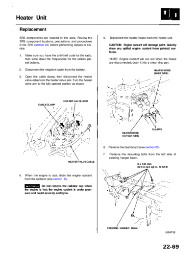
>> Download RL9604S22069A documenatation <<
Text preview - extract from the document
              Main Menu                 Table of Contents


Heater Unit
 Replacement
 SRS components are located in this area. Review the           5.    Disconnect the heater hoses from the heater unit.
 SRS component locations, precautions, and procedures
 in the SRS (section 24) before performing repairs or ser-           CAUTION: Engine coolant will damage paint. Quickly
 vice.                                                               rinse any spilled engine coolant from painted sur-
                                                                     faces.
 1.   Make sure you have the anti-theft code for the radio,
      then write down the frequencies for the radio's pre-           NOTE: Engine coolant will run out when the hoses
      set buttons.                                                   are disconnected; drain it into a clean drip pan.

 2.   Disconnect the negative cable from the battery.                                                    HEATER HOSE
                                                                                                         (INLET SIDE)
 3.   Open the cable clamp, then disconnect the heater
      valve cable from the heater valve arm. Turn the heater
      valve arm to the fully opened position as shown.


                                     HEATER VALVE ARM
                CABLE CLAMP


                                                                                                       CLAMPS
                                                                              HEATER HOSE
                                                                              (OUTLET SIDE)


                                                               6.    Remove the dashboard (see section 20).

                                                               7.    Remove the mounting bolts from the left side of
                                                                     steering hanger beam.
                                        HEATER VALVE CABLE
                                                                                          8 x 1.25 mm
                                                                                          22 N-m (2.2 kgf-m, 16 Ibf-ft)


 4.   When the engine is cool, drain the engine coolant
      from the radiator (see section 10).

                   Do not remove the radiator cap when
      the engine is hot; the engine coolant is under pres-
      sure and could severely scald you.


                                                                    STEERING HANGER BEAM
             Main Menu                  Table of Contents


Heater Unit
 Replacement (cont'd)
 8. Remove the mounting bolt and the mounting nuts              11. Remove the bolt and the cruise control unit. Discon-
    from the right side of the steering hanger beam,                nect the connectors from the mode control motor
    then remove the steering hanger beam.                           and the air mix control motor, then remove the clips
                                                                    and the A/C wire harness. Remove the mounting
                              6 x 1.0 mm                            bolt, the mounting nuts and the heater unit.
                              9.8 N-m (1.0 kgf-m, 7.2 Ibf-ft)
     STEERING HANGER BEAM
                                                                    CRUISE CONTROL UNIT


                                                                                                           HEATER UNIT
                                 8 x 1.25 mm
                                22 N-m (2.2 kgf-m, 16 Ibf-ft)
                                                                                           6 x 1.0 mm
                                                                                           9.8 N-m (1.0 kgf-m, 7.2 Ibf-ft)
 9. Remove the evaporator/blower unit (see page
                                                                   A/C WIRE HARNESS
    22-65).

 10. Remove the clips and the heater duct.


                HEATER DUCT
                                                                12. Install in the reverse order of removal. Make note of
                                                                    the following items.

                                                                       Apply sealant to the grommets.
                                                                       Do not interchange the inlet and outlet heater
                                                                       hoses.
                                                                       Make sure that the clamps are secure.
                                                                       Refill the cooling system with engine coolant
                                                                       (see section 10).
                                                                       Connect the heater valve cable, and make sure
                                                                       that it is properly adjusted (see page 22-72).
                                                                       Make sure that there is no air leakage.
                                                                       The PCM memory must be reset after reconnect-
                                                                       ing the battery (see page 11-125).
                                                                       Enter the anti-theft code for the radio, then enter
                                                                       the customer's radio station presets.
◦ Jabse Service Manual Search 2026 ◦ Jabse Pravopis ◦ onTap.bg ◦ Other service manual resources online : Fixya ◦ eServiceinfo