Service Manuals, User Guides, Schematic Diagrams or docs for : . Car Manuals Acura 3.5RL 1996-2004 Approved srm RL9604S23086A
<< Back | HomeMost service manuals and schematics are PDF files, so You will need Adobre Acrobat Reader to view : Acrobat Download Some of the files are DjVu format. Readers and resources available here : DjVu Resources
For the compressed files, most common are zip and rar. Please, extract files with Your favorite compression software ( WinZip, WinRAR ... ) before viewing. If a document has multiple parts, You should download all, before extracting.
Good luck. Repair on Your own risk. Make sure You know what You are doing.
Image preview - the first page of the document
>> Download RL9604S23086A documenatation <<
Text preview - extract from the document
Main Menu Table of Contents
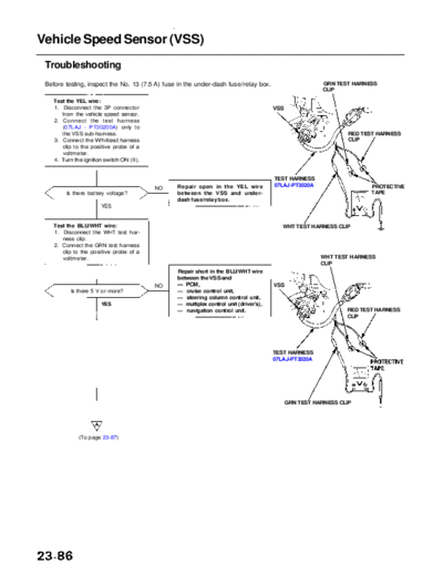
Vehicle Speed Sensor (VSS)
Troubleshooting
Before testing, inspect the No. 13 (7.5 A) fuse in the under-dash fuse/relay box. GRN TEST HARNESS
CLIP
Test the YEL wire:
1. Disconnect the 3P connector VSS
from the vehicle speed sensor.
2. Connect the test harness
(07LAJ - PT30200A) only to
the VSS sub-harness. RED TEST HARNESS
3. Connect the Whitest harness CLIP
clip to the positive probe of a
voltmeter.
4. Turn the ignition switch ON (II).
TEST HARNESS
Repair open in the YEL wire 07LAJ-PT3020A PROTECTIVE
NO
Is there battery voltage? between the VSS and under- TAPE
dash fuse/relay box.
YES
Test the BLU/WHT wire: WHT TEST HARNESS CLIP
1. Disconnect the WHT test har-
ness clip.
2. Connect the GRN test harness
clip to the positive probe of a
voltmeter. WHT TEST HARNESS
CLIP
Repair short in the BLU/WHT wire
between the VSS and
NO -- PCM, VSS
Is there 5 V or more? -- cruise control unit,
-- steering column control unit,
YES -- multiplex control unit (driver's),
-- navigation control unit. RED TEST HARNESS
CLIP
TEST HARNESS
07LAJ-PT3020A
GRN TEST HARNESS CLIP
(To page 23-87)
Main Menu Table of Contents
(From page 23-86)
PCM CONNECTOR D (22P)
Test the GRN/BLU wire:
1. Turn the ignition switch OFF.
2. Disconnect the test harness.
3. Disconnect the PCM 22P con- Wire side of (GRN/BLK)
nector. female terminals
4. Check for continuity between
the PCM 22P connector No. 22
terminal and VSS 3P connec-
tor No. 1.
(GRN/BLU)
Wire side of
NO Repair open in the GRN/BLU female terminals
Is there continuity?
wire between the VSS and PCM.
VSS 3P CONNECTOR
YES
Test the VSS:
1. Turn the ignition switch OFF.
2. Raise the front of the vehicle,
and support it with safety
stands.
3. Put the vehicle in neutral with
the ignition switch ON (II).
4. Slowly rotate one wheel with
the other wheel blocked.
Does voltage pulse from 0 to NO
Replace the VSS.
approx. 5 V or more?
YES GAUGE ASSEMBLY 22P CONNECTOR "A"
Speedometer Test:
1. Disconnect the 22P connector
"A" from the gauge assembly.
2. Touch a probe to the BLU/ Wire side of
WHT wire, and connect it to female terminals
body ground through a volt- (BLU/WHT)
meter.
3. Slowly rotate one wheel with
the other wheel blocked.
NO Repair open in the BLU/WHT
Does the meter indicate pulsing
wire between the VSS and the
voltage?
speedometer.
YES
Replace the speedometer.
◦ Jabse Service Manual Search 2026 ◦ Jabse Pravopis ◦ onTap.bg ◦ Other service manual resources online : Fixya ◦ eServiceinfo