Service Manuals, User Guides, Schematic Diagrams or docs for : . Car Manuals Dodge Durango 1998-2000 Approved Dodge Durango 2000 00dn_3
<< Back | HomeMost service manuals and schematics are PDF files, so You will need Adobre Acrobat Reader to view : Acrobat Download Some of the files are DjVu format. Readers and resources available here : DjVu Resources
For the compressed files, most common are zip and rar. Please, extract files with Your favorite compression software ( WinZip, WinRAR ... ) before viewing. If a document has multiple parts, You should download all, before extracting.
Good luck. Repair on Your own risk. Make sure You know what You are doing.
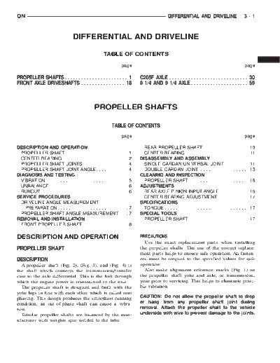
Image preview - the first page of the document

>> Download 00dn_3 documenatation <<
Text preview - extract from the document
DN                                                                                                 DIFFERENTIAL AND DRIVELINE                       3-1


                                   DIFFERENTIAL AND DRIVELINE
                                                       TABLE OF CONTENTS

                                                                     page                                                                           page

PROPELLER SHAFTS . . . . . . . . . . . . . . . . . . . . . . . 1                  C205F AXLE . . . . . . . . . . . . . . . . . . . . . . . . . . . . . 30
FRONT AXLE DRIVESHAFTS . . . . . . . . . . . . . . . . 18                         8 1/4 AND 9 1/4 AXLE . . . . . . . . . . . . . . . . . . . . . 59


                                                 PROPELLER SHAFTS

                                                            TABLE OF CONTENTS
                                                                     page                                                                           page

DESCRIPTION AND OPERATION                                                           REAR PROPELLER SHAFT . . . . . . . . . . . . . . . . . 10
  PROPELLER SHAFT . . . . . . . . . . . . . . . . . . . .            .   .   .1     CENTER BEARING . . . . . . . . . . . . . . . . . . . . . . . 11
  CENTER BEARING . . . . . . . . . . . . . . . . . . . . .           .   .   .2   DISASSEMBLY AND ASSEMBLY
  PROPELLER SHAFT JOINTS . . . . . . . . . . . . . .                 .   .   .4     SINGLE CARDAN UNIVERSAL JOINT . . . . . . . . . 11
  PROPELLER SHAFT JOINT ANGLE . . . . . . . . .                      .   .   .4     DOUBLE CARDAN JOINT . . . . . . . . . . . . . . . . . . 13
DIAGNOSIS AND TESTING                                                             CLEANING AND INSPECTION
  VIBRATION . . . . . . . . . . . . . . . . . . . . . . . . . . .    ...5           PROPELLER SHAFT . . . . . . . . . . . . . . . . . . . . . . 16
  UNBALANCE . . . . . . . . . . . . . . . . . . . . . . . . . .      ...6         ADJUSTMENTS
  RUNOUT . . . . . . . . . . . . . . . . . . . . . . . . . . . . .   ...6           REAR AXLE PINION INPUT ANGLE . . . . . . . . . . . 16
SERVICE PROCEDURES                                                                  CENTER BEARING ADJUSTMENT. . . . . . . . . . . . 17
  DRIVELINE ANGLE MEASUREMENT                                                     SPECIFICATIONS
    PREPARATION . . . . . . . . . . . . . . . . . . . . . . .        ...7           TORQUE . . . . . . . . . . . . . . . . . . . . . . . . . . . . . . . 17
  PROPELLER SHAFT ANGLE MEASUREMENT.                                 ...7         SPECIAL TOOLS
REMOVAL AND INSTALLATION                                                            PROPELLER SHAFT . . . . . . . . . . . . . . . . . . . . . . 17
  FRONT PROPELLER SHAFT . . . . . . . . . . . . . .                  ...8

DESCRIPTION AND OPERATION                                                         PRECAUTIONS
                                                                                    Use the exact replacement parts when installing
PROPELLER SHAFT                                                                   the propeller shafts. The use of the correct replace-
                                                                                  ment parts helps to ensure safe operation. All fasten-
DESCRIPTION                                                                       ers must be torqued to the specified values for safe
   A propeller shaft (Fig. 2), (Fig. 3), and (Fig. 4) is                          operation.
the shaft which connects the transmission/transfer                                  Also make alignment reference marks (Fig. 1) on
case to the axle differential. This is the link through                           the propeller shaft yoke and axle, or transmission,
which the engine power is transmitted to the axle.                                yoke prior to servicing. This helps to eliminate possi-
   The propeller shaft is designed and built with the                             ble vibration.
yoke lugs in line with each other which is called zero
phasing. This design produces the smoothest running                               CAUTION: Do not allow the propeller shaft to drop
condition, an out-of-phase shaft can cause a vibra-                               or hang from any propeller shaft joint during
tion.                                                                             removal. Attach the propeller shaft to the vehicle
   Tubular propeller shafts are balanced by the man-                              underside with wire to prevent damage to the joints.
ufacturer with weights spot welded to the tube.
3-2      PROPELLER SHAFTS                                                                                   DN
DESCRIPTION AND OPERATION (Continued)


          Fig. 1 Reference Marks on Yokes
1
◦ Jabse Service Manual Search 2024 ◦ Jabse Pravopis ◦ onTap.bg ◦ Other service manual resources online : Fixya ◦ eServiceinfo