Service Manuals, User Guides, Schematic Diagrams or docs for : . Car Manuals Dodge Neon 1997.1999.2000.2004 Approved Dodge Neon 1997 EPL_8B
<< Back | HomeMost service manuals and schematics are PDF files, so You will need Adobre Acrobat Reader to view : Acrobat Download Some of the files are DjVu format. Readers and resources available here : DjVu Resources
For the compressed files, most common are zip and rar. Please, extract files with Your favorite compression software ( WinZip, WinRAR ... ) before viewing. If a document has multiple parts, You should download all, before extracting.
Good luck. Repair on Your own risk. Make sure You know what You are doing.
Image preview - the first page of the document

>> Download EPL_8B documenatation <<
Text preview - extract from the document
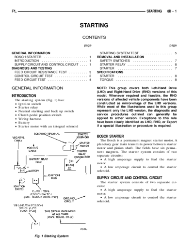
 NEGATIVE
      CABLE
  SWITCH            CABLE
                  BATTERY
                SWITCH       FEED    ONLY)
       SWITCH CLUTCH SOLENOID TERMINAL
                BATTERY PEDAL IGNITION
                    POSITION ALL CIRCUIT
                                     FEED
                             TRANSMISSION        CIRCUIT      NOID
IGNITION (AUTO. TRANS. ONLY) THISTIMES (MAN. TRANS. ONLY) STARTERCON-
                                              GROUND AT RELAY MOTOR
                                                            STARTER
                                                              NECTOR
PARK/NEUTRAL POSITIVE (MAN. RELAY POSITION GROUNDEDSTARTER SOLE-


PL                                                                                                                STARTING   8B - 1


                                                            STARTING
                                                              CONTENTS

                                                                page                                                          page

GENERAL INFORMATION                                                      STARTING SYSTEM TEST . . .               .............. 5
  BOSCH STARTER . . . . . . . . . . . . . . . . . . .       .... 1      REMOVAL AND INSTALLATION
  INTRODUCTION . . . . . . . . . . . . . . . . . . . .      .... 1       SAFETY SWITCHES . . . . . . .            .............. 7
  SUPPLY CIRCUIT AND CONTROL CIRCUIT                        .... 1       STARTER RELAY . . . . . . . . . .        .............. 8
DIAGNOSIS AND TESTING                                                    STARTER . . . . . . . . . . . . . . .    .............. 7
  FEED CIRCUIT RESISTANCE TEST . . . . . .                  .... 3      SPECIFICATIONS
  CONTROL CIRCUIT TEST . . . . . . . . . . . . .            .... 2       STARTER . . . . . . . . . . . . . . .    .............. 8
  FEED CIRCUIT TEST . . . . . . . . . . . . . . . . .       .... 4       TORQUE . . . . . . . . . . . . . . . .   .............. 8

GENERAL INFORMATION                                                     NOTE: This group covers both Left-Hand Drive
                                                                        (LHD) and Right-Hand Drive (RHD) versions of this
INTRODUCTION                                                            model. Whenever required and feasible, the RHD
  The starting system (Fig. 1) has:                                     versions of affected vehicle components have been
◦ Jabse Service Manual Search 2024 ◦ Jabse Pravopis ◦ onTap.bg ◦ Other service manual resources online : Fixya ◦ eServiceinfo