Service Manuals, User Guides, Schematic Diagrams or docs for : . Car Manuals Dodge Neon 1997.1999.2000.2004 Approved Dodge Neon 1997 EPL_8G
<< Back | HomeMost service manuals and schematics are PDF files, so You will need Adobre Acrobat Reader to view : Acrobat Download Some of the files are DjVu format. Readers and resources available here : DjVu Resources
For the compressed files, most common are zip and rar. Please, extract files with Your favorite compression software ( WinZip, WinRAR ... ) before viewing. If a document has multiple parts, You should download all, before extracting.
Good luck. Repair on Your own risk. Make sure You know what You are doing.
Image preview - the first page of the document

>> Download EPL_8G documenatation <<
Text preview - extract from the document
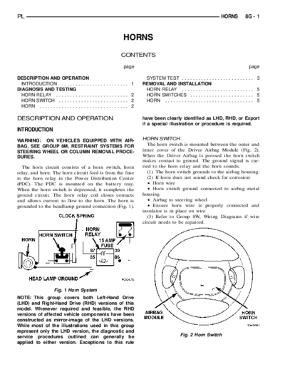
 15    FUSE
        AMP              HORN RELAY      HORN SWITCH
                                          HORN         CLOCK SPRING           AIRBAG MODULE
                                                                                HORN SWITCH
                HEAD LAMP GROUND


PL                                                                                                                  HORNS   8G - 1


                                                             HORNS
                                                            CONTENTS

                                                             page                                                             page

DESCRIPTION AND OPERATION                                              SYSTEM TEST . . . . . . . . . . . .        .............. 3
  INTRODUCTION . . . . . . . . . . .           ............. 1        REMOVAL AND INSTALLATION
DIAGNOSIS AND TESTING                                                  HORN RELAY . . . . . . . . . . . .         .............. 5
  HORN RELAY . . . . . . . . . . . . .         ............. 2         HORN SWITCHES . . . . . . . . .            .............. 5
  HORN SWITCH . . . . . . . . . . . .          ............. 2         HORN . . . . . . . . . . . . . . . . . .   .............. 5
  HORN . . . . . . . . . . . . . . . . . . .   ............. 2

DESCRIPTION AND OPERATION                                             have been clearly identified as LHD, RHD, or Export
                                                                      if a special illustration or procedure is required.
INTRODUCTION
WARNING: ON VEHICLES EQUIPPED WITH AIR-                               HORN SWITCH
BAG, SEE GROUP 8M, RESTRAINT SYSTEMS FOR                                 The horn switch is mounted between the outer and
STEERING WHEEL OR COLUMN REMOVAL PROCE-                               inner cover of the Driver Airbag Module (Fig. 2).
DURES.                                                                When the Driver Airbag is pressed the horn switch
                                                                      makes contact to ground. The ground signal is car-
  The horn circuit consists of a horn switch, horn                    ried to the horn relay and the horn sounds.
relay, and horn. The horn circuit feed is from the fuse                  (1) The horn switch grounds to the airbag housing.
to the horn relay in the Power Distribution Center                       (2) If horn does not sound check for corrosion:
(PDC). The PDC is mounted on the battery tray.
◦ Jabse Service Manual Search 2024 ◦ Jabse Pravopis ◦ onTap.bg ◦ Other service manual resources online : Fixya ◦ eServiceinfo